City rail traffic traction system

An urban rail transit and traction system technology, applied in the field of urban rail transit traction systems, can solve problems such as potential safety hazards and increase project cost, and achieve the effect of reducing project cost and potential safety hazards.

Inactive Publication Date: 2016-08-31
CRRC DALIAN R & D CO LTD
View PDF4 Cites 8 Cited by
  • Summary
  • Abstract
  • Description
  • Claims
  • Application Information

AI Technical Summary

Problems solved by technology

[0005] The purpose of the present invention is to provide a traction system for urban rail transit, which is used to solve certain safety problems in the way

Method used


Image

  • City rail traffic traction system
  • City rail traffic traction system
  • City rail traffic traction system

Examples


Embodiment 1

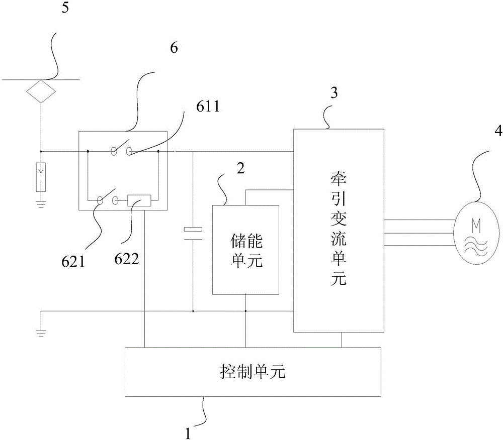
[0024] figure 1 The structural representation of the urban rail transit traction system provided for Embodiment 1 of the present invention, such as figure 1 As shown, the urban rail transit traction system provided by this embodiment includes: a control unit 1, an energy storage unit 2, a traction converter unit 3 and a traction motor 4, wherein the traction converter unit 3 is connected to the two direct currents of the external power supply unit 5 Between the busbars, the energy storage unit 2 is respectively connected to a DC busbar of the external power supply unit 5 and the traction converter unit 3, the energy storage unit 2 is used to store the electric energy provided by the external power supply unit 5, and the traction converter unit 3 is respectively connected to the control unit 1 is connected to the traction motor 4, and the control unit 1 is used to control the traction converter unit 3 to charge and store and / or discharge the energy storage unit 2, and convert t...

Embodiment 2

[0030] On the basis of the above examples, if figure 1 As shown, the urban rail transit traction system provided by this embodiment also includes: a switch switching unit 6 connected between the external power supply unit 5 and the traction converter unit 3, and the switch switching unit 6 includes: a first switch branch and a first switch branch connected in parallel with each other. The second switch branch, wherein the first switch branch includes a first switch 611 , and the second switch branch includes a second switch 621 and a current limiting resistor 622 connected in series. The switch switching unit 6 is also connected to the control unit 1 , and the control unit 1 is used to control the closing or opening of the first switch 611 and the second switch 621 .

[0031] Specifically, when the train decelerates and enters the station, the control unit 1 controls the second switch 621 to close, the current-limiting resistor 622 performs current-limiting charging control, t...


PUM


Abstract

The invention discloses a city rail traffic traction system. The city rail traffic traction system comprises a control unit, an energy storing unit, a traction current converting unit and a traction motor, wherein the traction current converting unit is connected between two direct current buses of an external power supply unit; the energy storing unit is connected with the direct current buses of the external power supply unit and the traction current converting unit; the energy storing unit is used for storing electric energy provided by the external power supply unit; the traction current converting unit is connected with the control unit and the traction motor; the control unit is used for controlling the traction current converting unit to perform charging and energy storing and/or discharging and energy releasing on the energy storing unit, so that direct current electric energy stored in the energy storing unit is converted to alternate current electric energy which is outputted to the traction motor to drive a train to operate. According to the city rail traffic traction system provided by the invention, when the train approaches a station and parks, the energy storing unit is charged; during the running of the train, electric energy stored in the energy storing unit is used for the train, and an uninterrupted contact line is not needed to be adopted for supplying electricity to the train, so that the project cost is reduced, and potential safety hazards caused by the uninterrupted contact line are also reduced.

Description

technical field [0001] The invention relates to the technical field of power traction, in particular to an urban rail transit traction system. Background technique [0002] Urban rail transit mainly refers to urban subway, urban express rail, light rail, tram, etc. The basic function of the traction system of urban rail transit is to provide power drive for the operation of urban rail trains. [0003] In the prior art, urban rail transit generally adopts the method of continuous power receiving, and provides uninterrupted electric energy for the train along with the operation of the train through the use of overhead catenary or ground power supply rail. Correspondingly, the current traction system of urban rail transit generally adopts the main circuit topology of "inverter + traction motor". The function of the traction motor is to convert electrical energy into mechanical energy to drive the operation of the urban rail train. [0004] However, the traction system of the...

Claims


Application Information

Patent Timeline
IPC IPC(8): B60L11/18H02J7/34
CPCB60L50/53B60L53/20B60L2200/26H02J7/345B60L50/60Y02T10/70Y02T10/7072Y02T90/14
Inventor 车向中郭建斌姜涛马晨普
Owner CRRC DALIAN R & D CO LTD
Why Eureka
Try Eureka