
Walking pushing system

A technology of jacking and jacking, which is applied in the erection/assembly of bridges, bridges, buildings, etc. It can solve the problems of large work and placement space, complex sliding box structure, and large work space, so as to save bridge construction costs and expand scalability Strong, small workspace effect

Inactive Publication Date: 2016-08-31
GUIZHOU ROAD & BRIDGE GRP +1
View PDF7 Cites 5 Cited by
  • Summary
  • Abstract
  • Description
  • Claims
  • Application Information

AI Technical Summary

Problems solved by technology

But it has the following defects: 1. The structure of the slideway and the slide box is complex, large in size, heavy in weight, difficult to process, high in cost, and requires a large working space
2. Each jacking unit needs 4 sets of jacking jacks and 4 sets of jacking jacks. Not only the equipment cost is high, but also the required work and installation space are large, and it is impossible to push the components that realize the I-beam and bolt splicing structure.

Method used


Image

  • Walking pushing system
  • Walking pushing system
  • Walking pushing system

Examples


Embodiment Construction

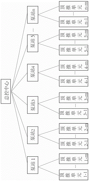
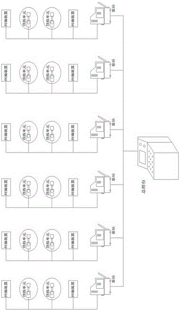
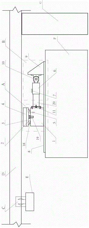
[0047] In this embodiment, a master control center, n hydraulic pump stations, and n×m pushing units are provided; the pushing units are as follows: figure 2 As shown, there is a lifting device A, a pushing device B, and a deviation correcting device C. The n×m pushing units are symmetrically distributed on both sides of the component axis, such as Figure 9 shown.

[0048] The lifting device A is provided with a lifting jack 1, a spherical plate 2, a comb plate 3, a backing plate 4, and a displacement sensor 5; The top of the piston 18 of the lifting jack 1 is a concave spherical surface, and the spherical plate 2 is as Figure 6 , 7 As shown, the bottom end is a convex spherical surface, which matches the concave spherical surface of the piston 18. The spherical plate 2 and the jacking jack piston 18 are kept centered by the bolt 19 arranged at the center of the circle, so that the spherical plate 2 can swing along the spherical surface , to adjust the self-leveling and...


PUM


Abstract

The invention discloses a walking pushing system. A power device comprises a plurality of hydraulic pump station single bodies. Each hydraulic pump station single body is provided with a unit radial plunger pump capable of achieving multi-port and multi-pressure output, and each hydraulic pump station controls at least two pushing units. A main control center sends a command to each hydraulic pump station single body and controls each hydraulic pump station to work. Each pushing unit comprises a lifting device and a pushing device, wherein a lifting jack is fixed to the lifting device, and the upper portion of the lifting jack and a spherical plate are connected into a spherical concave-convex groove connection structure or an arc-shaped concave-convex groove connection structure. The walking pushing system has the advantages that continuous and synchronous working is achieved by achieving three-dimensional control over the multiple pushing units through one main control system, the control precision is high, the labor intensity is relieved, and the labor cost is reduced; the structure is compact and simple, disassembly and assembly are easy, the cost is low, and the working space is small; equipment does not need to be dismounted till the work is completed after being mounted once, and the defect that only advancing can be achieved and retreating cannot be achieved by a conventional pulling way is overcome; and a dynamic deviation correcting function is achieved, and deviation correction can be conducted in time in the advancing process.

Description

technical field [0001] The invention relates to the technical field of engineering construction machinery, in particular to a walking jacking system for the overall translation of large components. Background technique [0002] Continuous jacking technology has been more and more widely used in translational construction of large components. For long-span structures such as steel box girder jacking construction of bridges, the existing construction methods generally adopt continuous jacking or dragging, and the steel box girder or concrete girder needs to be temporarily reinforced with external cables, and the bridge is lifted. ;Using the form of steel strand traction, every time a section is pushed, the steel strand needs to be reinstalled. The construction process of this method is cumbersome, the cost is high, and it can only move forward but not backward. At the same time, the horizontal thrust or pulling force of repeated starting is unfavorable to the stress working c...

Claims


Application Information

Patent Timeline
Patent Type & Authority Applications(China)
IPC IPC(8): E01D21/06E01D2/04
CPCE01D21/06E01D2/04
Inventor 何志军方永桥李钊肖云罗意钟韩洪举彭力任开富陈明辉张昱秦桂芳黄志如余隆友陈超冯俊淋蔡礼杰廖海龙杨红发邓超李贻先
Owner GUIZHOU ROAD & BRIDGE GRP
Learn More