A cascaded thermoacoustic power generation device

A technology for power generation devices and generators, which is applied to machines/engines, mechanical equipment, mechanisms that generate mechanical power, etc., can solve the problems of large volume of cascade thermoacoustic engines, large energy loss of resonance tubes, and uncompact structure, and achieves The effect of compact structure, elimination of resonance tubes, and improved efficiency

Active Publication Date: 2018-11-09
TECHNICAL INST OF PHYSICS & CHEMISTRY - CHINESE ACAD OF SCI
View PDF8 Cites 0 Cited by
  • Summary
  • Abstract
  • Description
  • Claims
  • Application Information

AI Technical Summary

Problems solved by technology

[0006] The technical problem to be solved by the present invention is that the existing cascade thermoacoustic engine has large volume, uncompact structure, large energy loss caused by resonance tube, and low efficiency

Method used


Image

  • A cascaded thermoacoustic power generation device
  • A cascaded thermoacoustic power generation device
  • A cascaded thermoacoustic power generation device

Examples


Embodiment 1

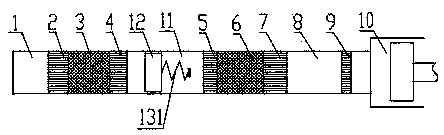
[0028] Such as figure 1 As shown, the cascade thermoacoustic power generation device provided in this embodiment includes a standing wave motor and a traveling wave motor, a phase-modulated resonator is connected between the standing wave motor and the traveling wave motor, and the traveling wave motor is A generator 10 is connected.

[0029] Wherein, the phase modulation resonator includes a phase modulation cylinder 11 , a phase modulation piston 12 arranged in the phase modulation cylinder 11 , and a return spring 131 connected to the phase modulation piston 12 . The standing wave engine includes a thermal cavity 1, a standing wave heater 2, a plate stack 3 and a standing wave water cooler 4 connected in sequence from left to right, wherein the standing wave water cooler 4 is connected to the left end of the phase-modulating cylinder 11 connected. The traveling wave engine includes a traveling wave main water cooler 5, a regenerator 6, a traveling wave heater 7, a thermal...

Embodiment 2

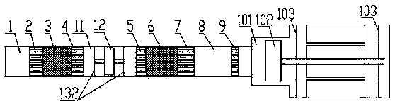
[0035] Such as figure 2 As shown, the cascade thermoacoustic power generation device provided by this embodiment includes a standing wave motor and a traveling wave motor, a phase-modulated resonator is connected between the standing wave motor and the traveling wave motor, and the traveling wave motor is There is a generator connected. Wherein the structures of the standing wave motor and the traveling wave motor are the same as that of Embodiment 1, only the structures of the phase modulation resonator and the generator are different.

[0036]Specifically, a phase modulation piston 12 is provided in the phase modulation cylinder 11 of the phase modulation resonator, and a return leaf spring 132 is respectively provided at both ends of the phase modulation piston 12, and the two ends of the phase modulation piston 12 The ends are respectively connected with the return leaf spring 132 through the piston rod. Since the phase modulation resonator adopts the return plate sprin...

Embodiment 3

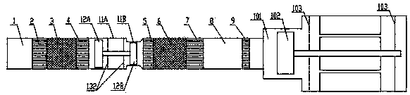
[0039] Such as image 3 As shown, the cascade thermoacoustic power generation device provided in this embodiment includes a standing wave motor and a traveling wave motor, a phase-modulated resonator is connected between the standing wave motor and the traveling wave motor, and the traveling wave motor is There is a generator connected. Wherein the structures of the standing wave motor, the traveling wave motor and the generator are the same as those of the second embodiment, only the structure of the phase-tuned harmonic oscillator is different.

[0040] Specifically, the phase modulation cylinder includes a first cylinder 11A and a second cylinder 11B, and the phase modulation piston includes a first phase modulation piston 12A and a second phase modulation piston 12B. The first phase-adjusting piston 12A and the second phase-adjusting piston 12B are correspondingly arranged in the first cylinder 11A and the second cylinder 11B, and the first phase-adjusting piston 12A and ...


PUM


Abstract

The invention relates to the technical field of thermo-acoustic power generation, in particular to a cascade thermo-acoustic power generation device. The cascade thermo-acoustic power generation device comprises a power generator, a standing wave engine and a traveling wave engine, wherein the traveling wave engine is connected with the power generator; a phase modulation resonator is connected between the standing wave engine and the traveling wave engine; the phase modulation resonator comprises a phase modulation air cylinder, a phase modulation piston which is arranged in the phase modulation air cylinder and adapted to the phase modulation air cylinder, and an elastic reset member which is connected with the phase modulation piston. According to the cascade thermo-acoustic power generation device, a resonant tube in the cascade thermo-acoustic engine in the prior art are replaced by the phase modulation resonator and the power generator, the impedance between the standing wave engine and the traveling wave engine are matched through the phase modulation resonator, and the power generator is used for modulating the phase in the traveling wave engine and outputting electric work, so that the whole cascade thermo-acoustic power generation device is more compact in structure and higher in power generation efficiency.

Description

technical field [0001] The invention relates to the technical field of thermoacoustic power generation, in particular to a cascaded thermoacoustic power generation device. Background technique [0002] A thermoacoustic engine is an energy conversion device that converts thermal energy into sound energy by using the thermoacoustic effect. It is mainly divided into a standing wave engine, a traveling wave engine, and a cascade thermoacoustic engine. Acoustic engine structure. [0003] The existing cascade thermoacoustic engine is mainly composed of a first resonance tube, a standing wave engine, a traveling wave engine and a second resonance tube. The standing wave motor and the traveling wave motor are located in the first resonant tube and the second resonant tube respectively. In order to reduce the flow loss, the diameter of the traveling wave motor is usually larger than that of the standing wave motor and the resonant tube. When heat is added to the standing wave heate...

Claims


Application Information

Patent Timeline
Patent Type & Authority Patents(China)
IPC IPC(8): F03G7/00
CPCF03G7/00
Inventor 胡剑英张丽敏罗二仓吴张华戴巍
Owner TECHNICAL INST OF PHYSICS & CHEMISTRY - CHINESE ACAD OF SCI
Why Eureka
Try Eureka