Eureka AIR delivers breakthrough ideas for toughest innovation challenges, trusted by R&D personnel around the world.

Friction heat furnace

A friction heat generation and friction block technology, applied in the field of heating furnaces, can solve problems such as hidden safety hazards, high cost, and large pollution, and achieve the effects of smooth friction, increased rotational speed, and frictional heating.

Inactive Publication Date: 2016-08-31
王海龙
View PDF7 Cites 3 Cited by
  • Summary
  • Abstract
  • Description
  • Claims
  • Application Information

AI Technical Summary

Problems solved by technology

[0003] The invention mainly aims at the problems of hidden safety hazards, high cost and heavy pollution in current heating, and provides a friction heat generating furnace

Method used


Image

  • Friction heat furnace
  • Friction heat furnace
  • Friction heat furnace

Examples


Embodiment 1

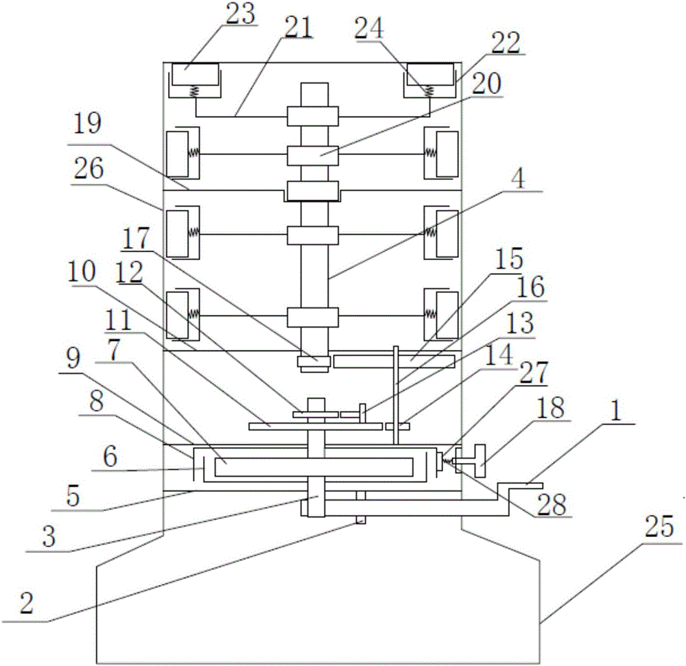
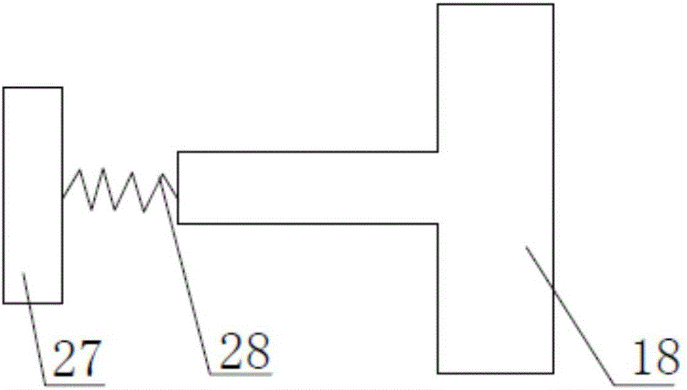
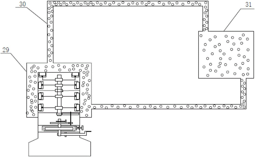
[0013] like figure 1 and figure 2 As shown, a friction heating furnace includes a base 25 and a housing 26 arranged on the base 25, wherein: it also includes a crank handle 1, a clockwork gear shaft 3, a central shaft 4, a clockwork case 6, a clockwork spring 7. Speed ​​regulating shell 8, No. 1 gear 11, No. 2 gear 12, non-return plate 13, No. 3 gear 14, No. 4 gear 15, gear shaft 16, central shaft gear 17 speed regulating switch 18, speed regulating friction plate 27 and the rotating assembly, the lower fixed bracket plate 5, the middle fixed bracket plate 9 and the upper fixed bracket plate 10 are successively provided in the shell 26 from bottom to top, and the crank handle 1 is arranged on the bottom of the lower fixed bracket plate 5 through the crank handle bracket 2. On the surface, the handle end of the crank handle 1 extends to the outer end of the shell, and the inner end of the crank handle 1 is connected to the lower end of the clockwork gear shaft 3 to drive the ...


PUM


Abstract

The invention belongs to the technical field of heating furnaces, in particular, relates to a friction heat furnace, and mainly solves the problems of potential safety hazards, high cost and heavy pollution in traditional heating. The friction heat furnace comprises such parts as a rocking handle, a spring gear shaft, a center shaft and a spring shell; the rocking handle is arranged on the lower surface of a lower fixed bracket plate through a rocking handle bracket; the spring shell is arranged on the upper surface of the lower fixed bracket plate; a spring is mounted in the spring shell; a speed adjusting shell is arranged on the spring gear shaft; a gear 1 is arranged at the middle upper part of the spring gear shaft; a gear 2 is fixedly arranged at the upper part of the spring gear shaft; a rotating disc coats the center shaft and rotates along with the center shaft; a friction block fixed frame is arranged at the outer end part of each connecting rod; friction blocks are arranged in the friction block fixed frames; and the inner end surfaces of the friction blocks are connected into the friction block fixed frames through springs.

Description

technical field [0001] The invention belongs to the technical field of heating furnaces, and in particular relates to a friction heating furnace. Background technique [0002] In winter in the north, heating is an essential issue for every family, especially in rural areas. Nowadays, heating basically relies on coal fires or electric heating, but there are problems of high cost and heavy pollution, and to a certain extent There are also security risks. Contents of the invention [0003] The invention mainly aims at the problems of hidden safety hazards, high cost and heavy pollution in the current heating, and provides a friction heat generating furnace. [0004] The technical scheme that the present invention takes for solving the above problems is: [0005] A friction heating furnace, comprising a base, and a shell set on the base, including: a crank handle, a clockwork gear shaft, a central shaft, a clockwork case, a clockwork spring, a speed regulating case, the firs...

Claims


Application Information

Patent Timeline
Patent Type & Authority Applications(China)
IPC IPC(8): F24D15/00
CPCF24D15/00F24D2200/30
Inventor 王海龙王淑敏王健王淑婷
Owner 王海龙
Why Eureka
Eureka Blog
Learn More