Method for reducing active sonar detecting blind area

A technology of active sonar and blind area, applied in the field of sonar and radar, it can solve the problem of slow update of target data, shorten the required time, improve the detection efficiency, and achieve the effect of low cost

Active Publication Date: 2016-08-31
INST OF ACOUSTICS CHINESE ACAD OF SCI
View PDF9 Cites 5 Cited by
  • Summary
  • Abstract
  • Description
  • Claims
  • Application Information

AI Technical Summary

Problems solved by technology

The disadvantage of this method is that each launch can only achieve optimal detection for a specific distance range, and multiple pulse cycles are required to c

Method used


Image

  • Method for reducing active sonar detecting blind area
  • Method for reducing active sonar detecting blind area
  • Method for reducing active sonar detecting blind area

Examples


Embodiment 1

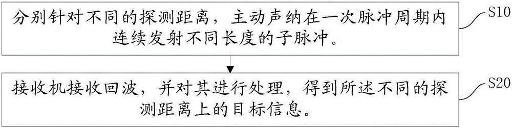
[0028] figure 1 A schematic flowchart of a method for reducing blind spots in active sonar detection provided by Embodiment 1 of the present invention is shown. like figure 1 Said, the method includes the following steps:

[0029] S10, for different detection distances, the active sonar continuously emits sub-pulses of different lengths within a pulse period.

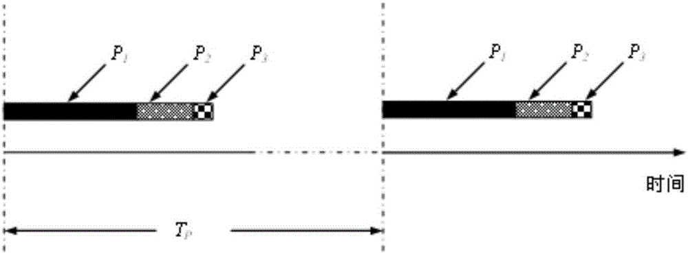
[0030] Preferably, in order to make the sub-pulses independent of each other, the sub-pulses of different lengths in the pulse train transmitted by the active sonar within one pulse period adopt code division and / or frequency division design. In order to further reduce the impact of the active pulse on the detection blind area of ​​the system, when the active sonar continuously transmits sub-pulses of different lengths within a pulse period, the transmission method adopted is: the short sub-pulse is in front and the long sub-pulse is in the back.

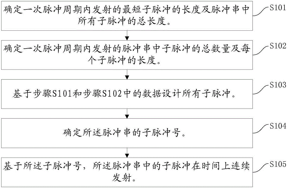
[0031] specifically, figure 2 A schematic flow chart of the active ...


PUM


Abstract

The invention relates to a method for reducing an active sonar detecting blind area. In one embodiment, the method comprises the steps of S10, for aiming at different detecting distances, continuously transmitting subpulses with different lengths by an active sonar in one subpulse period; and S20, receiving an echo by a receiver, processing the echo and obtaining object information on different detecting distances. The method has advantages of reducing influence of the blind area in long-distance of the active sonar, updating objective information in a whole maximal detecting distance in one-time emission, improving active detecting efficiency and detecting capability to moving objects in different speeds, and effectively improving detecting probability in a whole ranging area. Besides, the method does not require additional equipment through just changing a pulse transmission mode and an echo processing mode of the active solar. Low realization cost and potential application value are realized.

Description

technical field [0001] The invention relates to the technical field of sonar and radar, in particular to a method for reducing blind spots in active sonar detection. Background technique [0002] In the field of sonar and radar, blind spots are often a concern. Taking the combined active sonar as an example, one reason for the blind zone is that the active transmitting pulse needs to leave the surface of the transducer after the pulse time length T, and the transmitted signal will directly enter the receiving hydrophone. The resulting blind zone distance is d B = cT / 2, c is the speed of sound. Another reason is that the strong reverberation generated by the reflection of water bodies and interfaces makes the close-range targets submerged in the reverberation background. The above reasons all lead to receiver detection saturation, detection performance degradation, and blind spots. [0003] The T value of a typical sonar is generally a few milliseconds to a few seconds. ...

Claims


Application Information

Patent Timeline
IPC IPC(8): G01S7/524G01S7/527
CPCG01S7/524G01S7/527
Inventor 吴永清鄢社锋
Owner INST OF ACOUSTICS CHINESE ACAD OF SCI
Why Eureka
Try Eureka