
Corrugated interlocking armoring machine roller shaping guide belt mechanism

A technology of armoring machine and guide belt, which is applied in the field of corrugated interlocking armoring machine roller shaping guide belt mechanism, which can solve the problems of the influence of product roundness, high machine noise, and large heat generation, and achieve the maximum increase in line speed, convenience and observation and decontamination, the effect of frictional heat is small

Active Publication Date: 2017-09-19
HEFEI TIANQIN MECHANICAL & ELECTRICAL CO LTD
View PDF3 Cites 0 Cited by
  • Summary
  • Abstract
  • Description
  • Claims
  • Application Information

AI Technical Summary

Problems solved by technology

[0002] At present, in electrical machinery, the belt guide mechanism involving corrugated interlocking armoring machines generally adopts upper guide plate and lower guide plate. After changing from the dynamic rolling type to the pressing material, it needs to be transported to the winding forming mechanism along the tangential direction. The current structure is that the guide belt and the forming member are fixed together, and at the same time meet the requirements of the forming center and the center of rotation of the machine and the requirements of the tangential guide belt. Difficult, experienced operators need to spend a lot of time to adjust and fasten, otherwise the stability of winding forming will be poor, the roundness of the product will be affected, the pressing material conveying will be in sliding friction contact with the upper and lower guide plate sections, the heat will be large, and a large amount of aluminum will be produced at the same time. powder and other metal dust, the machine noise is loud, kerosene or emulsion atomization lubrication and cooling are required, the surface of the product is severely scratched, the working environment and the health of the operator are affected to a certain extent, and the maximum linear speed of the shaping guide belt is restricted.

Method used


Image

  • Corrugated interlocking armoring machine roller shaping guide belt mechanism
  • Corrugated interlocking armoring machine roller shaping guide belt mechanism

Examples


Embodiment Construction

[0009] The present invention will be described in further detail below with specific embodiments in conjunction with the accompanying drawings

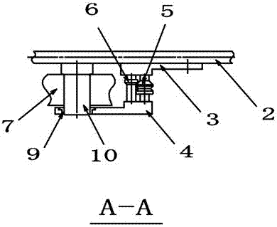
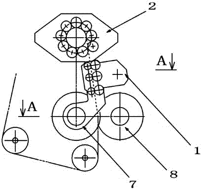
[0010] Such as figure 1 , figure 2 The new structure of corrugated interlocking armoring machine roller shaping guide belt shown is composed of shaping guide belt mechanism 1, winding forming mechanism 2, guide belt fixing plate 3, steering fixing plate 4, active pressing roll 7, driven pressing Roller 8, driven press roll shaft 10, its shaping guide belt mechanism 1 is set between the winding forming mechanism 2, active pressing roll 7, driven pressing roll 8, installed under the winding forming mechanism 2 A guide belt fixing plate 3, and a direction adjustment fixing plate 4 is arranged in parallel with the guide belt fixing plate 3, wherein three pairs of V-groove tapered edge shaping shaft rollers 5 and belts are installed between the guide belt fixing plate 3 and the direction adjustment fixing plate 4 Cone edge shaping suppo...


PUM


Abstract

The invention relates to a corrugated interlocking armoring machine roller shaping guide belt mechanism, which consists of a shaping guide belt mechanism (1), a winding forming mechanism (2), a guide belt fixing plate (3), an adjustment fixing plate (4), and an active pressing Composed of rolling (7), driven pressing type rolling (8) and driven pressing type rolling shaft (10), the beneficial effect of the present invention is: using the conduction band gap formed by the respective tapered sides of the two shaft rollings, the pressing The hypotenuse of the shape material is oriented to achieve accurate orientation. The guide belt is seamlessly connected with the winding forming mechanism, which is beneficial to winding forming. Because of the rolling contact, the frictional heat is small, and the maximum linear speed of the conveying shape material can be effectively increased. The resulting metal There is very little powder, the noise of the conduction belt is small, no lubrication and cooling are required, which greatly reduces the pollution of the working environment, and the surface of the workpiece is smooth and beautiful without scratches.

Description

Technical field: [0001] The invention relates to a corrugated interlocking armoring machine in which a spiral corrugated interlocking metal protective layer is wound on the outer diameter of the cable to protect cables in electrical machinery, a roller shaping guide belt mechanism is used to replace the sliding friction guide belt mechanism. Background technique: [0002] At present, in electrical machinery, the belt guide mechanism involving corrugated interlocking armoring machines generally adopts upper guide plate and lower guide plate. After changing from the dynamic rolling type to the pressing material, it needs to be transported to the winding forming mechanism along the tangential direction. The current structure is that the guide belt and the forming member are fixed together, and at the same time meet the requirements of the forming center and the center of rotation of the machine and the requirements of the tangential guide belt. Difficult, experienced operators ...

Claims


Application Information

Patent Timeline
Patent Type & Authority Patents(China)
IPC IPC(8): H01B13/26B21D1/02B21D43/00
CPCB21D1/02B21D43/003H01B13/2686
Inventor 谢泽生
Owner HEFEI TIANQIN MECHANICAL & ELECTRICAL CO LTD
Learn More