Zinc-air battery pack employing vertical circulation of electrolyte

A battery pack and electrolyte technology, applied in the field of electrolyte vertical circulation zinc-air battery pack, can solve problems such as insufficient current intensity, achieve easy replacement and disassembly, improve the effect of insufficient current intensity, and improve electrolyte dilution

Active Publication Date: 2016-08-31
HEBEI UNIV OF TECH
View PDF3 Cites 6 Cited by
  • Summary
  • Abstract
  • Description
  • Claims
  • Application Information

AI Technical Summary

Problems solved by technology

The placement of the zinc anode plate and the air cathode plate in the battery pack improves the defect of insufficient current intensity caused by the placement of the electrodes

Method used


Image

  • Zinc-air battery pack employing vertical circulation of electrolyte
  • Zinc-air battery pack employing vertical circulation of electrolyte
  • Zinc-air battery pack employing vertical circulation of electrolyte

Examples


Embodiment 1

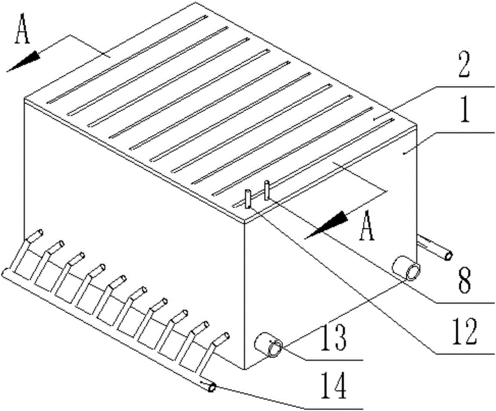
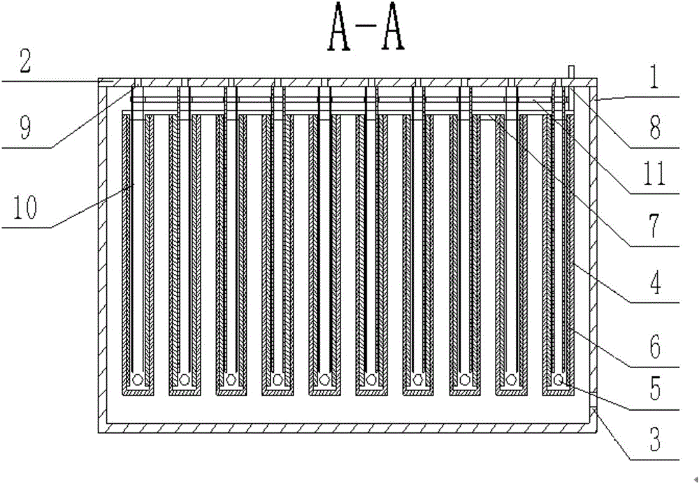
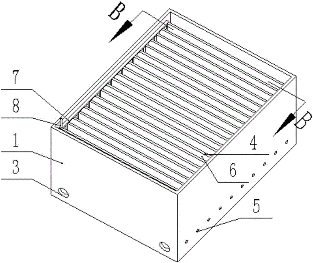
[0020] A kind of electrolytic solution vertical circulation zinc-air battery pack (see Figure 1-7 , referred to as the battery pack), including box 1, top plate 2, zinc pole support frame 4, zinc anode plate 6, zinc pole conductive sheet 7, anode terminal 8, air cathode plate 10, air electrode conductive sheet 11 and cathode terminal 12;

[0021] The box body 1 and the top plate 2 are sealed and connected to form the main part of the battery pack; the zinc pole support frame 4 is a U-shaped structure with an open upper end, a closed lower end, and vertically placed side plates; the outer side of the zinc pole support frame 4 The wall is sealed and connected to the inner side wall of the box body 1, and there are gaps between the bottom and top of the zinc pole support frame 4 and the box body 1; there is no contact between each zinc pole support frame 4; the bottom of the side wall of the box body 1 is open There is an electrolyte return hole 5, the hole is located inside th...

Embodiment 2

[0024] An electrolyte vertical circulation zinc-air battery pack (battery pack for short), comprising a box body 1, a top plate 2, a zinc pole support frame 4, a zinc anode plate 6, a zinc pole conductive sheet 7, an anode terminal 8, and an air cathode plate 10. Air electrode conductive sheet 11 and cathode terminal 12;

[0025] The box 1 and the top plate 2 are sealed and connected to form the main part of the battery pack; the zinc pole support frame 4 is a V-shaped structure with an open upper end and a closed lower end, and the two side plates form an angle of 45° with the horizontal plane; the zinc pole support The outer wall of the frame 4 is sealed and connected with the inner wall of the box body 1, and there are gaps between the bottom and top of the zinc pole support frame 4 and the box body 1; there is no contact between each zinc pole support frame 4; the box body 1 There is an electrolyte return hole 5 at the bottom of the side wall, and the opening position is l...


PUM


Abstract

The invention discloses a zinc-air battery pack employing vertical circulation of an electrolyte. The zinc-air battery pack comprises a box body, a top plate, zinc electrode support frames, zinc anode plates, zinc electrode conducting plates, an anode terminal, air cathode plates, an air electrode conducting plate and a cathode terminal. The zinc anode plates and the air cathode plates are arranged at an included angle which is greater than 0 and smaller than 180 degrees from the horizontal plane, so that the defect of insufficient current intensity caused by an electrode putting way is improved. Meanwhile, a detachable form is adopted by the zinc anode plates and the air cathode plates, so that late maintenance, replacement and disassembly are relatively simple and convenient. Certain gaps exist between the zinc anode plates and the air cathode plates; after the height of the horizontal liquid level of the electrolyte exceeds the heights of the zinc anode plates, the electrolyte drops down along the gaps in a form similar to a waterfall due to the action of gravity; the electrolyte contacts the zinc anode plates and the air cathode plates in the dropping process; and batteries are discharged immediately. Therefore, the space utilization rate of the battery pack is improved; and relatively high current density is generated.

Description

technical field [0001] The invention belongs to the field of battery pack assembly, and in particular relates to a vertical circulation zinc-air battery pack with electrolyte solution. Background technique [0002] Zinc-air batteries have become a research hotspot in recent years due to their high energy, high power density, safety and economy. Compared with lithium batteries, zinc-air batteries have higher energy and lower prices, making them the most valuable power batteries in the future. However, due to the limitations of existing zinc-air batteries, the discharge current density of zinc-air batteries cannot meet the requirements of market applications. In the article "Research on Air Electrode Arrangement in Zinc-air Batteries", Zhu Mei improved battery performance by changing the air electrode arrangement and optimizing electrolyte circulation. For example, after experimenting with horizontal and vertical arrangements of air electrodes, it was found that the maximum ...

Claims


Application Information

Patent Timeline
IPC IPC(8): H01M12/06
CPCH01M12/065
Inventor 关玉明邱子桢朱博肖艳军许波
Owner HEBEI UNIV OF TECH
Why Eureka
Try Eureka