Optimal configuration method for direct current magnetic bias suppressing device in direct current power transmission system

A technology of direct current transmission system and direct current bias, which is applied in the direction of circuit devices, AC network circuits, electrical components, etc., can solve the problems of increasing costs and workload, and the inability to obtain a direct current bias solution, so as to improve operation stability , to achieve the effect of comprehensively optimizing configuration, improving accuracy and protection efficiency

Inactive Publication Date: 2016-08-31
STATE GRID CORP OF CHINA +2
View PDF4 Cites 11 Cited by
  • Summary
  • Abstract
  • Description
  • Claims
  • Application Information

AI Technical Summary

Problems solved by technology

[0004] Due to the suppression of DC bias equipment connected to the grid, as a part of the AC grid, it will change the DC distribution of the AC system, which will have an impact on the equipment operation, protection devices and other equipment of the AC system. Therefore, only based on the existing engineering measurement values ​​or The simulation calculation of simple fixed operation mode cannot obtain a comprehensive solution for DC bias
Configure the DC bias suppression equipment by installing and testing, which may increase unnecessary costs and workload

Method used


Image

  • Optimal configuration method for direct current magnetic bias suppressing device in direct current power transmission system
  • Optimal configuration method for direct current magnetic bias suppressing device in direct current power transmission system
  • Optimal configuration method for direct current magnetic bias suppressing device in direct current power transmission system

Examples


Embodiment Construction

[0051] The following will clearly and completely describe the technical solutions in the embodiments of the present invention with reference to the accompanying drawings in the embodiments of the present invention. Obviously, the described embodiments are only some, not all, embodiments of the present invention. Based on the embodiments of the present invention, all other embodiments obtained by persons of ordinary skill in the art without making creative efforts fall within the protection scope of the present invention.

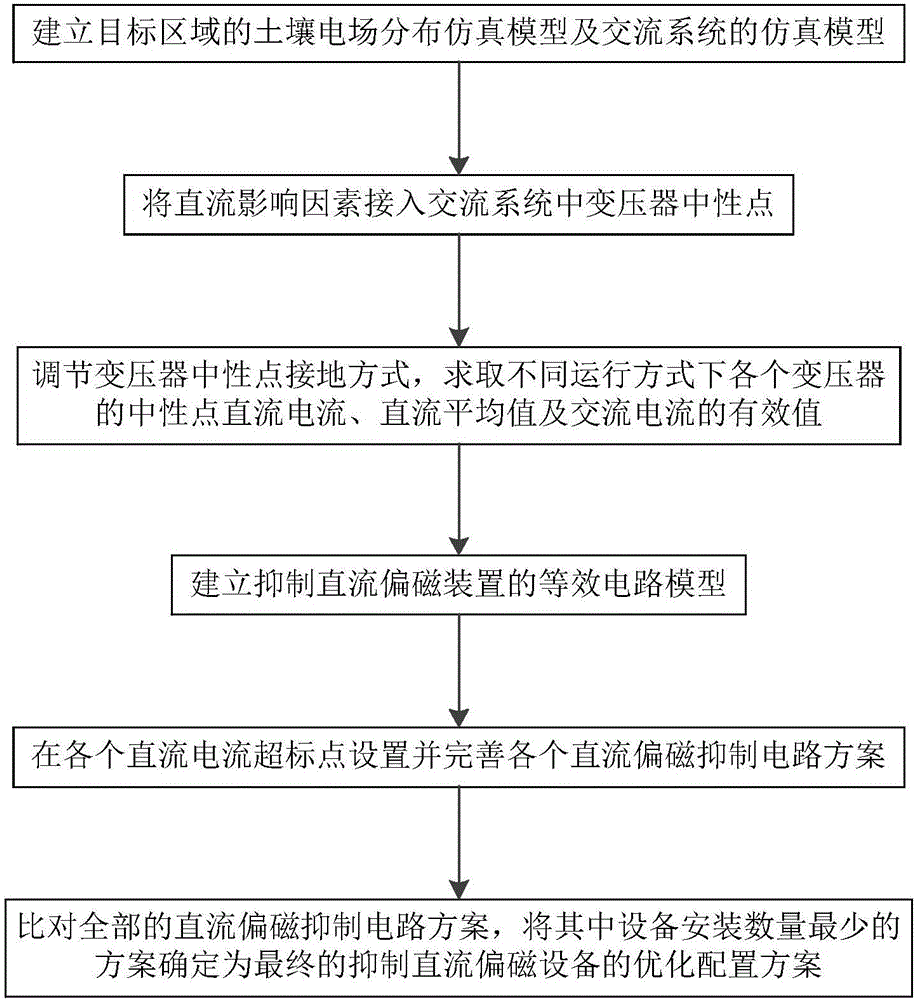
[0052] Such as figure 1 As shown, the present invention provides a method for optimal configuration of DC bias suppression equipment in a DC power transmission system. The method optimizes the configuration of the DC bias suppression equipment installed at the UHV DC grounding pole of the transformer in the DC power transmission system;

[0053] Including the following steps:

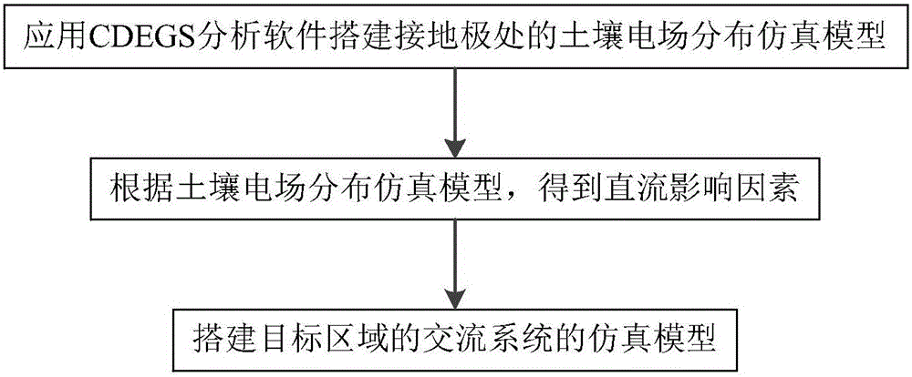
[0054] Step 1. Establish the simulation model of the soil electric field distrib...


PUM


Abstract

The invention provides an optimal configuration method for a direct current magnetic bias suppressing device in a direct current power transmission system. A soil electric field distribution and alternating current system simulation model is built, direct current influence factors access a voltage transformer neutral point, a voltage transformer neutral point grounding mode is adjusted and evaluated, an equivalent circuit model of the direct current magnetic bias suppressing device is built, all direct current magnetic bias suppressing circuit solutions are set and improved, and a final solution with a minimum number of installed devices is determined. The method brought forward in the invention can effectively and reliably realize overall optimal configuration of the direct current magnetic bias suppressing device in the direct current power transmission system; while no extra cost is caused and not extra workload is produced, an optimal device configuration solution can be put forward for a plurality of operation modes, an overall and effective basis is provided for configuration of the direct current magnetic bias suppressing device in the direct current power transmission system, configuration accuracy and protection efficiency of the direct current magnetic bias suppressing device in the direct current power transmission system can be effectively improved, and operation stability of the direct current power transmission system can be enhanced.

Description

technical field [0001] The invention relates to the field of ultra-high voltage direct current, in particular to an optimal configuration method for suppressing direct current bias equipment in a direct current transmission system. Background technique [0002] In the unipolar-to-ground or bipolar asymmetric operation mode of the DC transmission system, there may be thousands of amperes or even thousands of amperes of DC current flowing into the earth from the grounding electrode, forming a potential distribution in the soil, resulting in a certain range of AC system. There are different degrees of DC bias phenomenon in the transformer whose neutral point is directly grounded. [0003] In order to solve the DC bias problem of the transformer, the common DC bias suppression equipment mainly adopts the methods of current limiting and DC blocking. The configuration schemes of the existing DC bias suppression equipment mainly come from the following two kinds: engineering pract...

Claims


Application Information

Patent Timeline
Patent Type & Authority Applications(China)
IPC IPC(8): H02J3/36
CPCH02J3/36H02J2003/365H02J2203/20Y02E60/60
Inventor 王天正王冬青王康宁曹楠俞华李冰王述仲陈翔宇马晓光侯鹏
Owner STATE GRID CORP OF CHINA
Why Eureka
Try Eureka