
A Method for Limiting the Overload Current of Voltage Source Converter

A voltage source converter, overload technology, applied in emergency protection circuit devices for limiting overcurrent/overvoltage, power transmission AC network, conversion of AC power input to AC power output, etc., can solve the problem of unsuitable current Limit requirements, the system cannot work properly, etc., to achieve the effect of eliminating insufficient water cooling capacity

Active Publication Date: 2018-11-23
NR ELECTRIC CO LTD +1
View PDF5 Cites 0 Cited by
  • Summary
  • Abstract
  • Description
  • Claims
  • Application Information

AI Technical Summary

Problems solved by technology

[0003] At present, the topology of the flexible DC transmission voltage source converter mostly adopts the modular multi-level converter technology. Under the normal working state of the converter, the six bridge arms pass the current, and the switching devices of the module itself cause heat. It needs a certain water cooling capacity to lower the temperature to ensure the normal operation of the module. However, if the water cooling capacity is insufficient, the water temperature at the outlet of the valve will be too high and the system will not work normally. At this time, the water cooling control system detects that the water temperature is too high. The control system sends the water cooling overload limit current command
[0004] At present, after the upper computer receives the water-cooling overload limit current command, the processing method can generally adopt the method of reducing the operating DC current, or adopt the dynamic current limiting control method. The former is mostly used in the current source type traditional DC transmission method, and the latter belongs to the inner loop. Current limit, mostly used for transient current limit, has certain application limitations in voltage source converter overload current limit, because the bridge arm current of voltage source converter not only includes active components, but also includes reactive current Components, only after reducing the DC current can not fully meet the current target of the overload limit bridge arm, the transient current limit has a faster response speed, generally used for transient control, not suitable for the current limit requirements required by the overload

Method used


Image

  • A Method for Limiting the Overload Current of Voltage Source Converter
  • A Method for Limiting the Overload Current of Voltage Source Converter
  • A Method for Limiting the Overload Current of Voltage Source Converter

Examples


Embodiment Construction

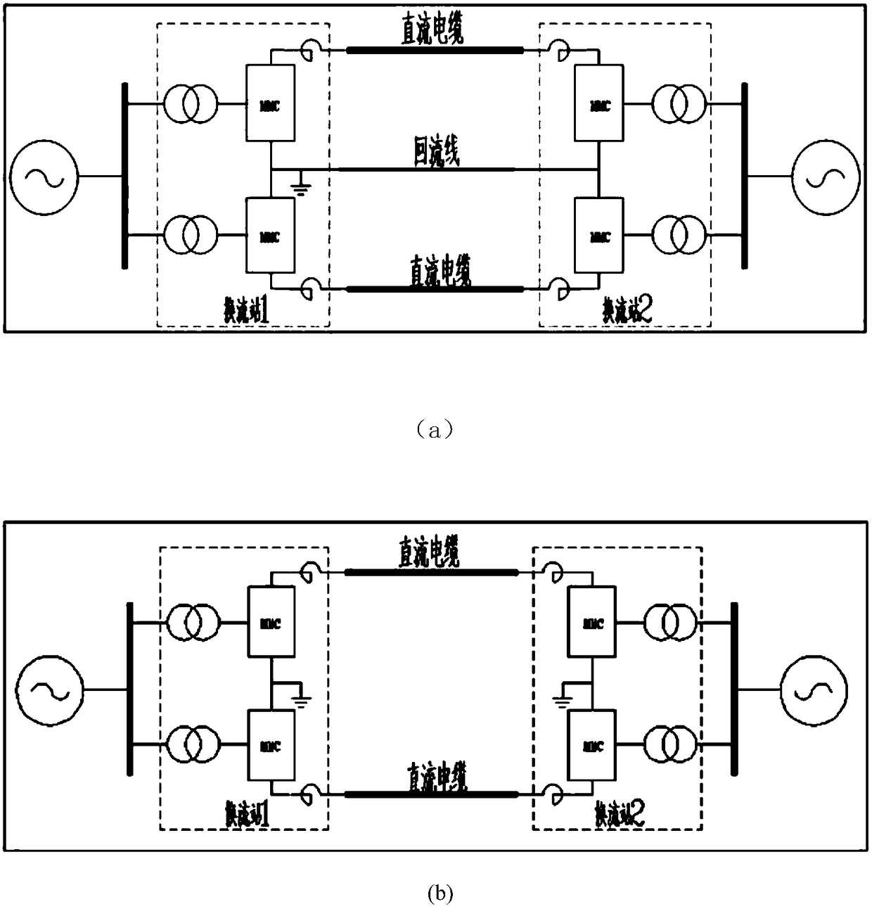
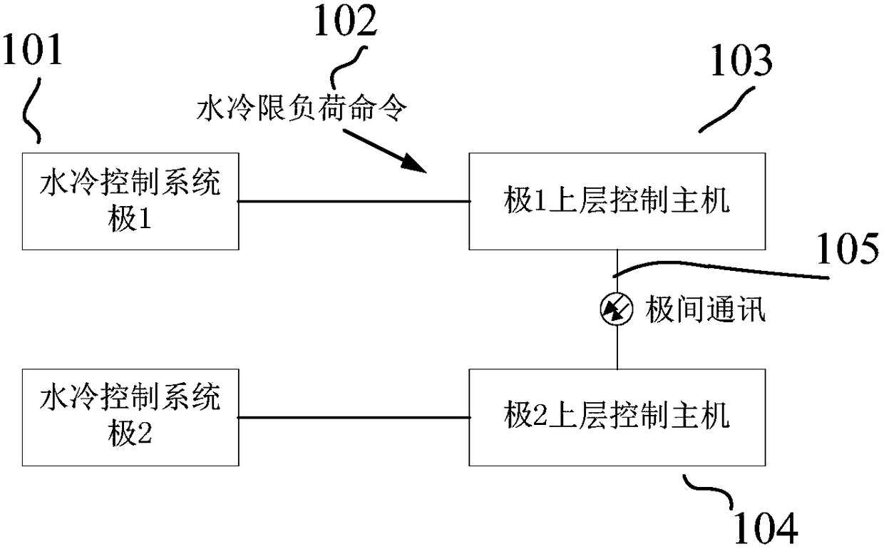
[0025] The purpose of the present invention is to provide a method for limiting the overload current of a voltage source converter. This method is applied to unipolar or bipolar topologies in HVDC flexible transmission systems, see figure 2 As shown, when the upper control host 103 of pole 1 receives the overload limit current command 102 from the water-cooling control system 101, it changes the active power and reactive power commands at the same time according to the specified slope, so that the absolute value of the bridge arm current of the converter follows the fixed slope It can reduce the active power and reactive power to 0 at the same time, and achieve the water-cooled load limit target of the converter by reducing the current of the bridge arm. This method can be used after the water-cooled overload limit power command received by the pole control system is released. Active power and reactive power keep the current value unchanged, and continue to decrease on the ba...


PUM


Abstract

The invention relates to an overload current limiting method of a voltage source converter. The voltage source converter is applied in the unipolar or bipolar topology of the flexible DC transmission system. When the pole control system receives the water-cooled overload limit current command, it changes the active power and reactive power commands at the same time according to the specified slope, so that the converter's The absolute value of the bridge arm current drops according to a fixed slope, and it can ensure that the active power and reactive power drop to 0 at the same time, so as to achieve the water-cooled load limit target of the converter by reducing the bridge arm current, and the water-cooled overload limit received by the pole control system After the power command is released, the current values ​​of active power and reactive power remain unchanged, and continue to decrease on the basis of the current power value after receiving the water-cooling overload limit power command next time, until it drops to 0 power. This method is applicable to the voltage source type In unipolar or bipolar topology, the function of water-cooling overload limit power is realized to ensure the safe operation of the converter valve when it is overloaded. The operation process is simple, reliable and easy to implement.

Description

technical field [0001] The invention belongs to the field of direct current transmission, and in particular relates to a method for limiting the overload current of a voltage source converter. Background technique [0002] Flexible DC transmission uses voltage source converters, which can independently adjust the transmission of active and reactive power, improve the transmission capacity of the AC system, and easily form a multi-terminal DC transmission system. And other application fields, have obvious competitiveness. [0003] At present, the topology of the flexible DC transmission voltage source converter mostly adopts the modular multi-level converter technology. Under the normal working state of the converter, the six bridge arms pass the current, and the switching devices of the module itself cause heat. It needs a certain water cooling capacity to lower the temperature to ensure the normal operation of the module. However, if the water cooling capacity is insuffici...

Claims


Application Information

Patent Timeline
Patent Type & Authority Patents(China)
IPC IPC(8): H02M1/32
CPCH02M1/32H02M1/327G05F1/66G05F1/70H02H5/041H02H7/1216H02H9/001H02J3/18H02J3/36H02M5/4585G01R21/002G01R21/003H02M1/0025H02M1/0012H02M7/4835Y02E40/30Y02E60/60
Inventor 胡兆庆董云龙卢宇李海英曹冬明
Owner NR ELECTRIC CO LTD
Learn More