
Wireless charging device

A wireless charging and battery technology, applied in circuit devices, battery circuit devices, current collectors, etc., can solve the problems of no temperature optimization and reduced user comfort, and achieve the effects of slowing down the temperature rise, eliminating hot spots, and enhancing comfort

Inactive Publication Date: 2016-08-31
SCENERAY
View PDF4 Cites 26 Cited by
  • Summary
  • Abstract
  • Description
  • Claims
  • Application Information

AI Technical Summary

Problems solved by technology

However, there is no optimization measure for the outer surface temperature of the case of the wireless charging device, that is to say, the temperature of the case of the charging device is still high, because the case will directly contact the user's skin or single clothes, thereby greatly reducing the comfort of the user

Method used


Image

  • Wireless charging device
  • Wireless charging device
  • Wireless charging device

Examples


Embodiment Construction

[0025] The present invention will be described in detail below in conjunction with specific embodiments shown in the accompanying drawings. However, these embodiments do not limit the present invention, and any structural, method, or functional changes made by those skilled in the art according to these embodiments are included in the protection scope of the present invention.

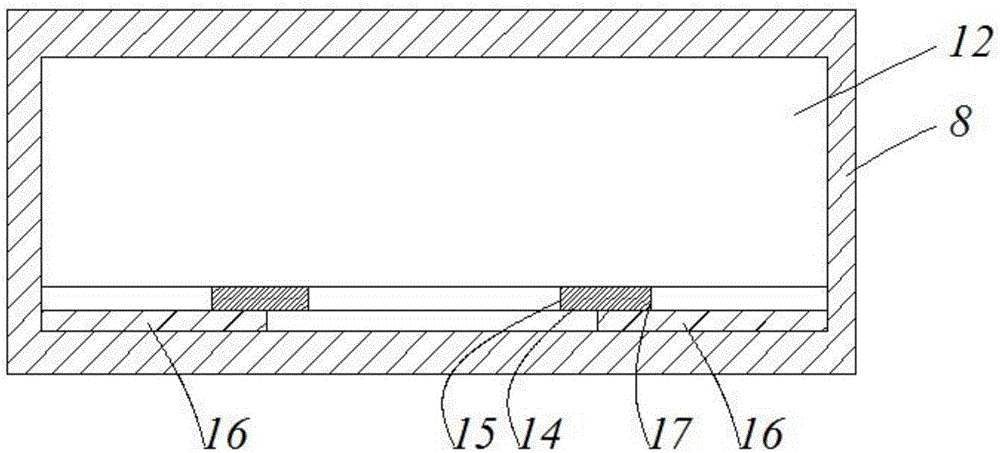
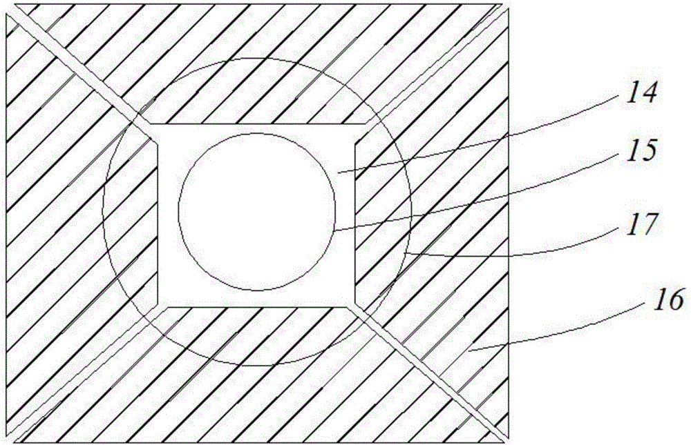
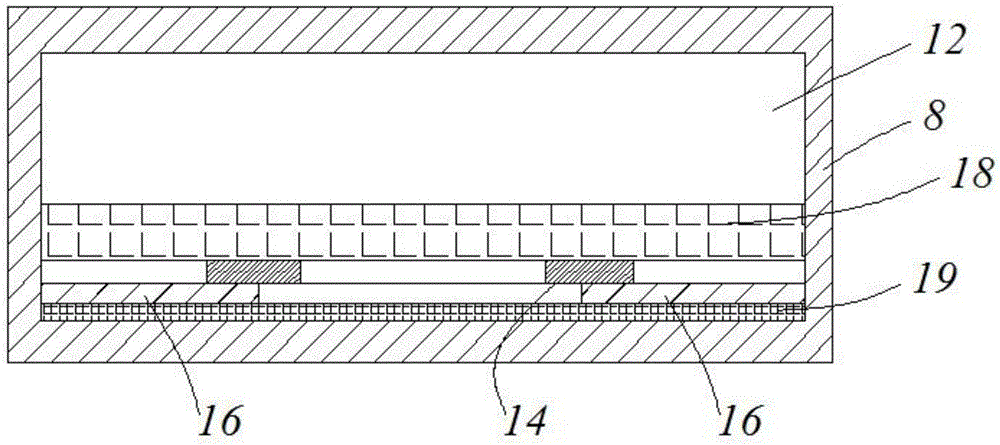
[0026] Such as figure 1 and figure 2 As shown, the present invention provides a first preferred embodiment, which discloses a wireless charging device. The wireless charging device includes a casing 8 , and a battery 12 and a primary coil 14 are arranged in the casing 8 . In addition, a heat dissipation layer 16 is disposed inside the casing 8 , and the heat dissipation layer 16 is disposed between the primary coil 14 and the casing 8 . In addition, adjacent to the battery 12, there are also PCB boards, auxiliary brackets, connecting devices, etc., which are not shown in the figure.

[0027] In thi...


PUM


Abstract

The invention discloses a wireless charging device, which comprises a shell, a battery arranged in the shell and a primary coil arranged in the shell, wherein a cooling layer is also arranged in the shell and is arranged between the primary coil and the shell. By the wireless charging device, the heat generated by the primary coil can be quickly diffused, so that the comfort degree during charging for a user is enhanced.

Description

technical field [0001] The invention relates to a wireless charging device. Background technique [0002] At present, wireless charging technology has been relatively popular, such as smart phones have adopted wireless charging, or implanted medical instruments have also adopted wireless charging. However, a large amount of heat will be generated during charging, which will have a negative impact on the user and greatly reduce the comfort of the user. In addition, the temperature of the battery increases, which will also affect the life of the battery. In order to solve the above problems, designers use a combination of materials with high thermal conductivity and high magnetic permeability in the existing wireless charging device to dissipate heat from the battery in the wireless charging device in an attempt to reduce the temperature of the battery. However, there is no optimization measure for the outer surface temperature of the outer shell of the wireless charging dev...

Claims


Application Information

Patent Timeline
Patent Type & Authority Applications(China)
IPC IPC(8): H05K7/20H02J7/00H02J50/10
CPCH05K7/20472H02J7/025H05K7/20481
Inventor 王畅
Owner SCENERAY
Learn More