
A support hydraulic vertical clamp

A hydraulic and vertical mounting technology, applied in the direction of clamping, supporting, manufacturing tools, etc., can solve the problems of unstable clamping force, unstable product quality, and loose positioning surface, so as to ensure consistency and transmission process Simple and convenient, ensuring stable and constant effect

Active Publication Date: 2017-12-29
鹰普(中国)有限公司
View PDF8 Cites 0 Cited by
  • Summary
  • Abstract
  • Description
  • Claims
  • Application Information

AI Technical Summary

Problems solved by technology

[0002] The workpiece clamping and positioning of the bracket of the existing machining center is positioned by the fixed mandrel, and the two sides are manually clamped. Its operation speed is slow, and the clamping force is unstable. Due to the positioning of the slender hole, the fixed core is often broken and bent, which may easily cause the positioning surface of the workpiece in the clamping process to be not tightly attached and the product quality to be unstable.

Method used


Image

  • A support hydraulic vertical clamp
  • A support hydraulic vertical clamp
  • A support hydraulic vertical clamp

Examples


Embodiment Construction

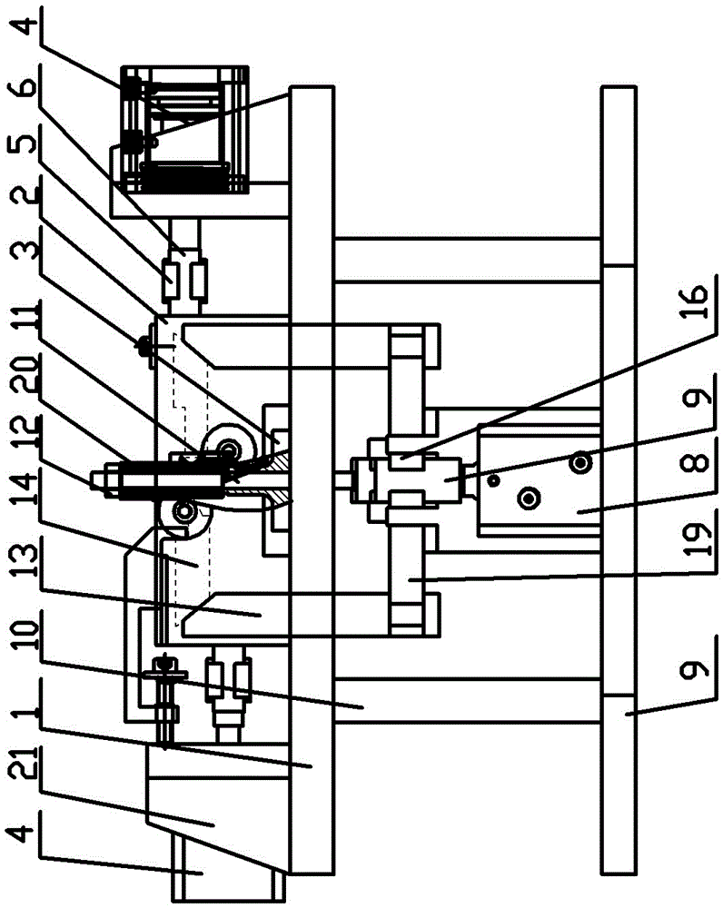
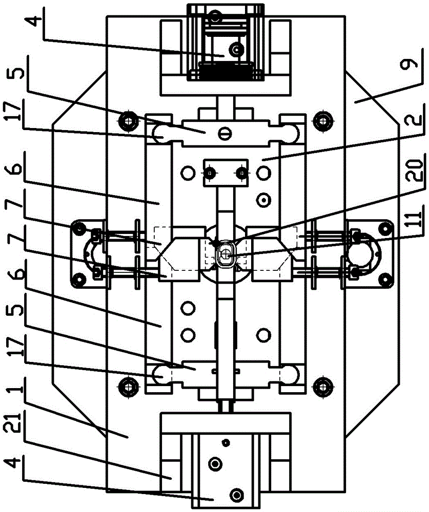
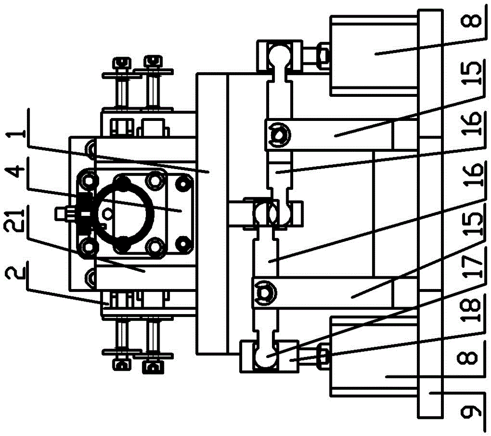
[0014] See figure 1 , figure 2 , image 3 As shown, a support hydraulic vertical clamping fixture, which includes a positioning base plate 1, a limit seat 2 is installed on the upper end of the positioning base plate 1, and a guide groove is opened in the limit seat 2, and the positioning base plate 1 is installed in the middle of the limit seat 2. There is a positioning block 3, and the left and right sides of the limit seat 2 are respectively equipped with a lateral compression cylinder 4 through a transverse seat 21, and the piston rod of the lateral compression cylinder 4 is connected to two side-by-side laterally arranged wedge mechanisms through the second hinge block 5 , the laterally arranged wedge mechanism includes a horizontal push block 6 and a lateral sliding clamping block 7 arranged in the guide groove of the limit seat 2; it is located at the lower end of the positioning base plate 1, and the front and rear ends of the limit seat 2 are respectively equipped w...


PUM


Abstract

The invention relates to the technical field of workpiece positioning structures in machining centers, in particular to a bracket hydraulic vertical adding fixture; and the bracket hydraulic vertical adding fixture can realize quick bracket clamping to improve the efficiency and to reduce the labor intensity of operators. A limiting base is mounted on the upper end surface of a positioning baseplate; a guide groove is formed in the limiting base; transverse pressing oil cylinders are respectively mounted on the left and right two sides of the limiting base; piston rods of the transverse pressing oil cylinders are connected with transverse wedge mechanisms; longitudinal pressing oil cylinders are respectively mounted at the front and back two ends of the limiting base and positioned at the lower end of the positioning baseplate; one longitudinal pressing oil cylinder is connected with a positioning rod through a first lever transmission mechanism; the positioning rod penetrates through the positioning baseplate; an annular groove is formed in the upper end part of the positioning rod, and is provided with a detachable pressing plate; the other longitudinal pressing oil cylinder is connected with a longitudinal wedge mechanism through a second lever transmission mechanism; and the longitudinal wedge mechanism includes a longitudinal push block and a longitudinal slide clamping block arranged in a guide groove of the limiting base.

Description

technical field [0001] The invention relates to the structural technical field of workpiece positioning in a machining center, in particular to a support hydraulic vertical clamping fixture. Background technique [0002] The workpiece clamping and positioning of the bracket of the existing machining center is positioned by the fixed mandrel, and the two sides are manually clamped. The operation speed is slow, and the clamping force is unstable. Due to the positioning of the elongated hole, the fixing core is often broken and bent, which may easily cause the positioning surface of the workpiece in the clamping process to be not tightly attached and the product quality to be unstable. Contents of the invention [0003] In order to solve the above problems, the present invention provides a bracket hydraulic vertical clamp, which can realize fast clamping of the bracket, improve efficiency, reduce the labor intensity of the operator, ensure the consistency of the pressing forc...

Claims


Application Information

Patent Timeline
Patent Type & Authority Patents(China)
IPC IPC(8): B23Q3/08
CPCB23Q3/062B23Q3/08
Inventor 彭宝金朱国宏房福州
Owner 鹰普(中国)有限公司
Learn More