
A powder feeding device

A feeding device, powder technology, applied in transportation and packaging, conveyors, rotary conveyors, etc., can solve the problems of compressed air consumption, difficulty in maintenance work, energy consumption, etc., and achieve reasonable structure and good reliability. , the effect of low cost

Active Publication Date: 2018-03-16
CHONGQING HENGYUAN POWDER METALLURGICAL PROD CO LTD
View PDF6 Cites 0 Cited by
  • Summary
  • Abstract
  • Description
  • Claims
  • Application Information

AI Technical Summary

Problems solved by technology

The use of cylinders must be equipped with corresponding pipelines, and at the same time consume compressed air, that is, consume energy
At the same time, the working characteristics of the cylinder determine that it must be repaired and replaced at regular intervals. Therefore, certain maintenance and operating costs are required.
Secondly, the constant volume chamber located at the lower part of the constant volume unloading device needs to be opened and closed with a certain structure, generally using a steel brush structure, which will fail due to frequent friction with the constant volume chamber and needs to be replaced regularly. Bring great difficulty to maintenance work

Method used


Image

  • A powder feeding device
  • A powder feeding device
  • A powder feeding device

Examples


Embodiment Construction

[0014] The present invention will be further described in detail below in conjunction with the accompanying drawings and examples. The following examples are explanations of the present invention and the present invention is not limited to the following examples.

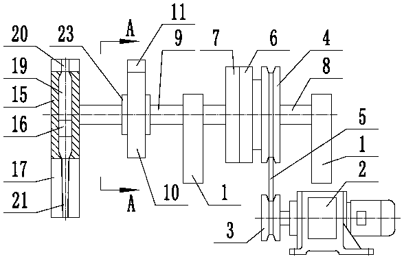
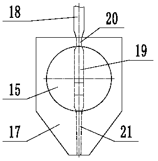
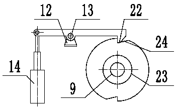
[0015] like figure 1 , figure 2 and image 3 As shown, a powder feeding device includes a frame 1, a driving motor 2, a driving pulley 3, a driven pulley 4, a driving belt 5, a first friction disc 6, a second friction disc 7, a first One support shaft 8, the second support shaft 9, positioning plate 10, positioning rod 11, positioning support 12, bearing pin 13, electromagnet 14, disc 15, plunger 16, disc support 17, material injection pipe 18, The first supporting shaft 8 is rotatably arranged on the frame 1, and the second supporting shaft 9 is also rotatably arranged on the frame 1. The first supporting shaft 8 and the second supporting shaft 9 are coaxial, The driven pulley 4 is coaxially arranged on the fir...


PUM


Abstract

The invention provides a powdery material supply device and belongs to the technical field of supply machines. The device comprises a first friction disk, a second friction disk, a positioning disk, a positioning rod, a round plate and a plunger, wherein a first supporting shaft and a second supporting shaft are coaxial; the first friction disk is arranged on one side of the first supporting shaft; the second friction disk is arranged on one side of the second supporting shaft; the first friction disk and the second friction disk are attached to each other; the round plate is coaxially fixed on the other side of the second supporting shaft and is rotationally arranged in a round plate support; a radial through hole is formed in the round plate, and opening diameters of the two ends of the through hole are smaller than that the opening diameter of the middle part of the through hole; the plunger is vertically glidingly arranged in the through hole; a material injection pipe is arranged above an inlet; the positioning disk is coaxially fixed on the second supporting shaft; the middle end of the positioning rod is hinged to a positioning supporting seat by the aid of a hinge pin; a positioning jaw is arranged at one end of the positioning rod; and the other end of the positioning rod is connected with an electromagnet. Quantitative supply of powdery materials is realized, and the device is reasonable in structure and good in stability.

Description

technical field [0001] The invention relates to the technical field of feeding machines, in particular to a powder feeding device. Background technique [0002] Feeding machine, also known as feeding machine, refers to a machine that can uniformly, regularly and continuously feed bulk and granular materials from the storage bin to the receiving device during the production process. In this type of machinery, powder feeding equipment is a common feeding machine, and in many cases, the feeding of powder needs to achieve quantitative supply. The feeding of common powder depends on the reciprocating movement of the cylinder at the top to open and close the constant-volume feeding chamber at the bottom, so as to realize the charging and discharging of powder into the constant-volume feeding chamber, so as to achieve Quantitative volume of powder is added to the designated place. The constant volume cutting device of this structure has been generally adopted in the world. Howev...

Claims


Application Information

Patent Timeline
Patent Type & Authority Patents(China)
IPC IPC(8): B65G29/00
CPCB65G29/00B65G2201/04
Inventor 宣永
Owner CHONGQING HENGYUAN POWDER METALLURGICAL PROD CO LTD
Learn More