Automatic detection robot system and detection method for road surface

A robot system and robot body technology, applied in the road surface autonomous detection robot system and detection field, can solve the problems of inability to evaluate the road surface condition, high labor intensity, low efficiency, etc., to reduce the impact of road traffic, economy and safety Performance improvement, good overall performance of the system

Inactive Publication Date: 2016-09-07
桂仲成
View PDF6 Cites 27 Cited by
  • Summary
  • Abstract
  • Description
  • Claims
  • Application Information

AI Technical Summary

Problems solved by technology

At present, the detection and evaluation of road surface conditions mainly rely on manual visual inspection, which mainly depends on experience, and the detection accuracy is poor
The alternative is to use manual instrument detection, which is better than visual data accuracy, but there are also the following problems: First, manual data collection is easily affected by manual operation errors, data accuracy cannot be guaranteed, and personal safety No guarantee; second, the rate of manual inspection is low, requiring a lot of manpower, labor-intensive and inefficient, and the inspection time is long, which affects th

Method used


Image

  • Automatic detection robot system and detection method for road surface
  • Automatic detection robot system and detection method for road surface
  • Automatic detection robot system and detection method for road surface

Examples


Embodiment 1

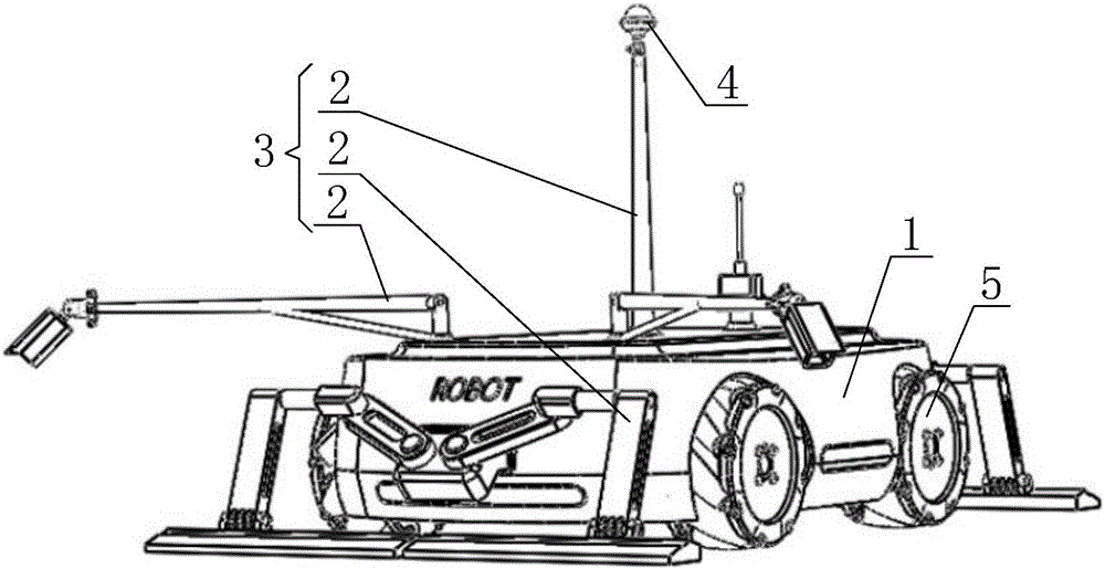
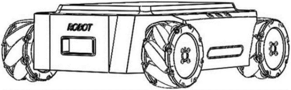
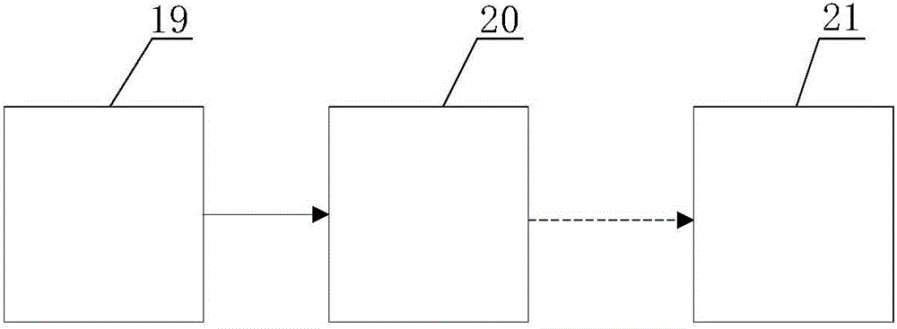
[0043] Embodiment 1 of the present invention: as figure 1 , figure 2 , image 3 with Figure 9 As shown, a road surface autonomous detection robot system includes a robot body 1 and a remote monitoring auxiliary system 21. The robot body 1 is provided with a control system 20, a non-destructive testing system 19 and an operating mechanism 3, and the operating mechanism 3 is installed on the robot body 1. Above, the non-destructive testing system 19 is connected to the operating mechanism 3, the control system 20 is electrically connected to the operating mechanism 3, and the control system 20 is electrically connected to the non-destructive testing system 19; the non-destructive testing system 19 includes a resistivity meter 9, and the operating mechanism 3 includes a telescopic mechanism 2 , the resistivity meter 9 is connected to the telescopic mechanism 2; the remote monitoring auxiliary system 21 includes a control cabinet 18, an operating console 14 and a monitoring s...

Embodiment 2

[0047] Embodiment 2: as figure 1 , figure 2 , image 3 with Figure 9 As shown, a road surface autonomous detection robot system includes a robot body 1 and a remote monitoring auxiliary system 21. The robot body 1 is provided with a control system 20, a non-destructive testing system 19 and an operating mechanism 3, and the operating mechanism 3 is installed on the robot body 1. Above, the non-destructive testing system 19 is connected to the operating mechanism 3, the control system 20 is electrically connected to the operating mechanism 3, and the control system 20 is electrically connected to the non-destructive testing system 19; the non-destructive testing system 19 includes a resistivity meter 9, and the operating mechanism 3 includes a telescopic mechanism 2 , the resistivity meter 9 is connected to the telescopic mechanism 2; the remote monitoring auxiliary system 21 includes a control cabinet 18, an operating console 14 and a monitoring screen 15, and the operati...

Embodiment 3

[0049] Embodiment 3: as figure 1 , figure 2 , image 3 with Figure 9 As shown, a road surface autonomous detection robot system includes a robot body 1 and a remote monitoring auxiliary system 21. The robot body 1 is provided with a control system 20, a non-destructive testing system 19 and an operating mechanism 3, and the operating mechanism 3 is installed on the robot body 1. Above, the non-destructive testing system 19 is connected to the operating mechanism 3, the control system 20 is electrically connected to the operating mechanism 3, and the control system 20 is electrically connected to the non-destructive testing system 19; the non-destructive testing system 19 includes a resistivity meter 9, and the operating mechanism 3 includes a telescopic mechanism 2 , the resistivity meter 9 is connected to the telescopic mechanism 2; the remote monitoring auxiliary system 21 includes a control cabinet 18, an operating console 14 and a monitoring screen 15, and the operati...


PUM


Abstract

The invention discloses an automatic detection robot system for a road surface. The automatic detection robot system for the road surface comprises a robot body and a remote monitoring auxiliary system. Information is transmitted between the robot body and the remote monitoring auxiliary system in a wireless communication way. A control system, a nondestructive detection system and an operation mechanism are arranged on the robot body. The operation mechanism is installed on the robot body. The nondestructive detection system is connected with the operation mechanism. The control system is electrically connected with the operation mechanism. The control system is electrically connected with the nondestructive detection system. The nondestructive detection system comprises a resistivity meter. The operation mechanism comprises a telescopic mechanism. The resistivity meter is connected with the telescopic mechanism. The invention further discloses a detection method for the road surface. By the adoption of the robot system, intelligent detection can be achieved, and since manual driving is not needed, the detection safety and the accuracy of detection data are improved; since various nondestructive detection sensors are integrated, comprehensive estimation of the road surface and the internal condition can be achieved at a time, the detection efficiency is greatly improved, and the influence of the trafficability of a road is also reduced.

Description

technical field [0001] The invention relates to a road surface detection device and method, in particular to a road surface autonomous detection robot system and detection method. Background technique [0002] After the expressway is completed, in order to ensure the safety and efficiency of traffic, it needs regular maintenance. With the rapid increase in the mileage of expressways in China and the increase in the service life of the roads, expressways have entered a period of equal emphasis on construction and maintenance. Expressways with more than 50,000 kilometers have generally entered the normal maintenance period after the defect liability period, and the overall personnel scale of the maintenance industry has grown rapidly. With the "Twelfth Five-Year Road Maintenance and Management Development Outline" of the Ministry of Communications, the proportion of major and medium repairs has been increased from 13% to 17%, and the proportion has increased by nearly 30%. In...

Claims


Application Information

Patent Timeline
IPC IPC(8): E01C23/01G01N17/00G01N15/08G01D21/02
CPCE01C23/01G01N15/08G01N17/006G01N21/88G01N29/048G01N29/14G01V11/00
Inventor 桂仲成
Owner 桂仲成
Why Eureka
Try Eureka