A water tank drainage device utilizing pressure difference for drainage

A technology of drainage device and pressure difference, which is applied to water supply devices, flushing equipment with water tanks, flushing toilets, etc., can solve the problem that the force value of pulling and sealing the water plate needs to be large, the number of times of use of the power supply battery is shortened, and it is not conducive to practical use. and other problems, to achieve the effect of good siphon effect, simple structure and easy design

Active Publication Date: 2019-03-26
XIAMEN R&T PLUMBING TECH
View PDF15 Cites 0 Cited by
  • Summary
  • Abstract
  • Description
  • Claims
  • Application Information

AI Technical Summary

Problems solved by technology

[0002] There are many drainage devices (drainage valves) on the market with various drainage principles and structures. Although most of these drainage devices have relatively reliable functions and stable drainage, they often require a large opening and closing force. For example, the common drain valve that pulls the water sealing plate in the valve body to open the drain port to realize drainage. Since the water pressure directly acts on the water sealing plate, the force required to lift the water sealing plate is very large, and it is very uncomfortable to use. Convenience, poor user experience, and when the drain valve that requires a large pulling force is designed as an electronic control type, the required motor power is also relatively large, which will shorten the number of times the power supply battery is used, which is not conducive to practical use

Method used


Image

  • A water tank drainage device utilizing pressure difference for drainage
  • A water tank drainage device utilizing pressure difference for drainage
  • A water tank drainage device utilizing pressure difference for drainage

Examples


no. 1 example

[0046] The first embodiment: (the pumping mechanism is a siphon assembly, and the siphon trigger assembly is manually controlled)

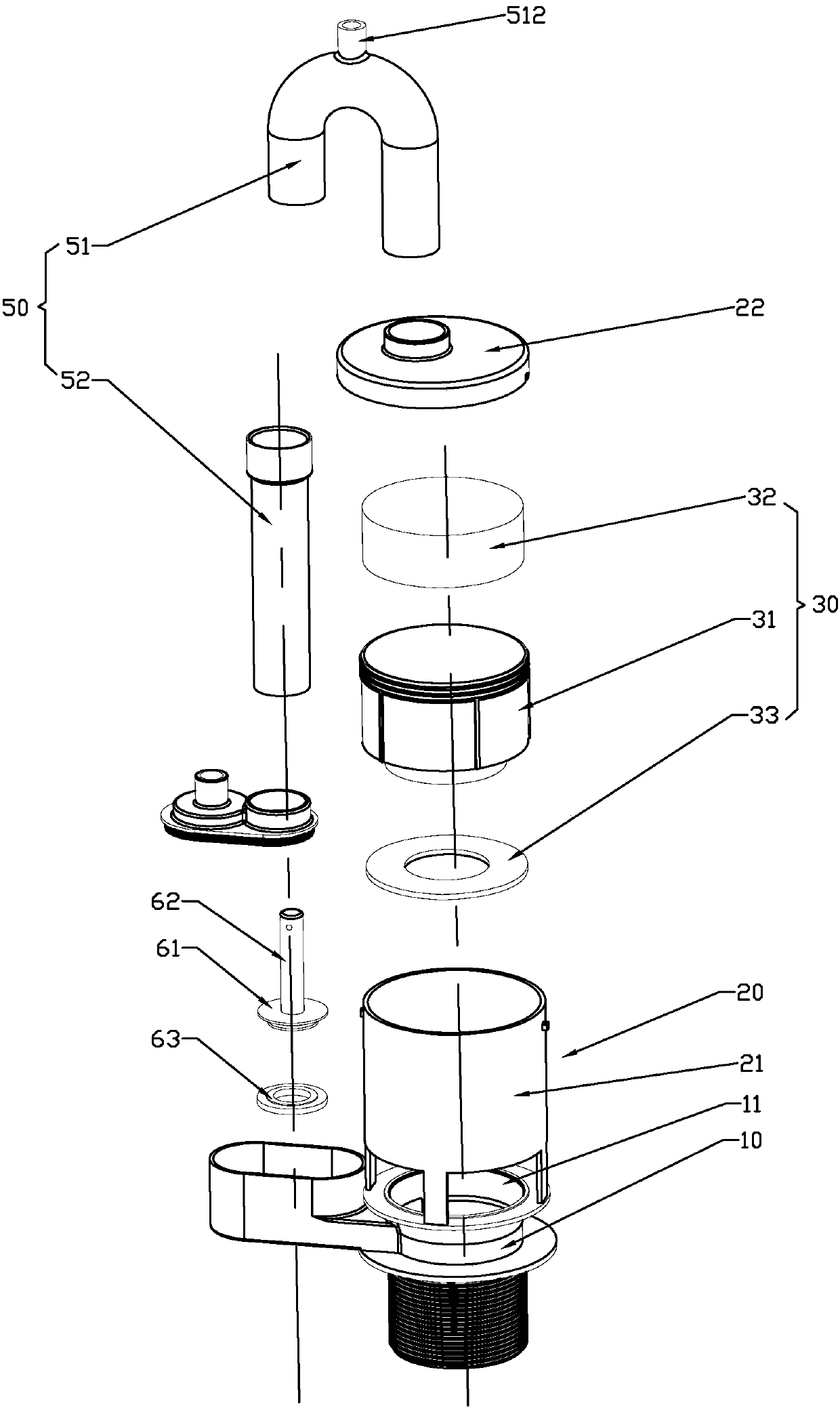
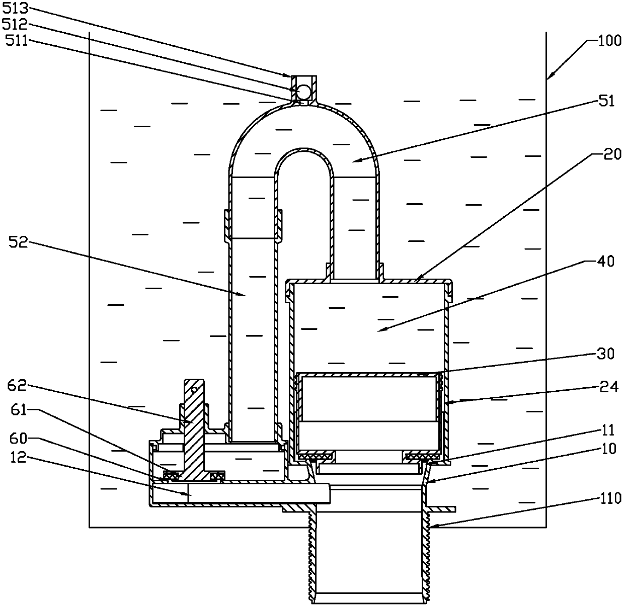
[0047] Such as Figure 1-3As shown, a water tank drainage device utilizing pressure difference in this embodiment includes a base 10, a casing 20, a floating body 30 and a pumping mechanism. The base 10 is fixed at the mounting hole 110 of the bottom wall of the water tank 100, and the drain 11 is provided on the base 10, which is also equivalent to that the drain 11 is arranged on the bottom wall of the water tank 100, or the base 10 may not be provided. , and the water outlet 11 is directly arranged on the bottom wall of the water tank 100 . The shell 20 is a hollow structure with an open bottom and is firmly connected with the base 10. In this embodiment, the shell 20 and the base 10 are integrally formed to achieve fixed fit. The bottom opening of the shell 20 is connected to the water outlet 11 and the inner cavity of the water tank They ar...

no. 2 example

[0055] Second embodiment: (the pumping mechanism is a siphon assembly, and the electric control chain moves to drive the siphon trigger assembly)

[0056] Such as Figure 4 As shown, the difference between this embodiment and the first embodiment is that this embodiment controls the movement of the chain 64 through the electric drive mechanism to drive the movement of the valve plate 61, specifically, the valve plate 61 cooperates with one end of the chain 64 through the connecting rod 62 , the other end of the chain 64 is coordinated with an electric drive mechanism, the electric drive mechanism can be a motor, the electric control structure is simple and feasible, and it is convenient to use. Of course, here, the manual drive mechanism can also be selected to pull the chain 64, and the rest of the undescribed structures and The working principle is consistent with that of the first embodiment, and will not be repeated here.

no. 3 example

[0057] The third embodiment: (the pumping mechanism is a siphon assembly, and the movement of the float is electrically controlled to drive the siphon trigger assembly)

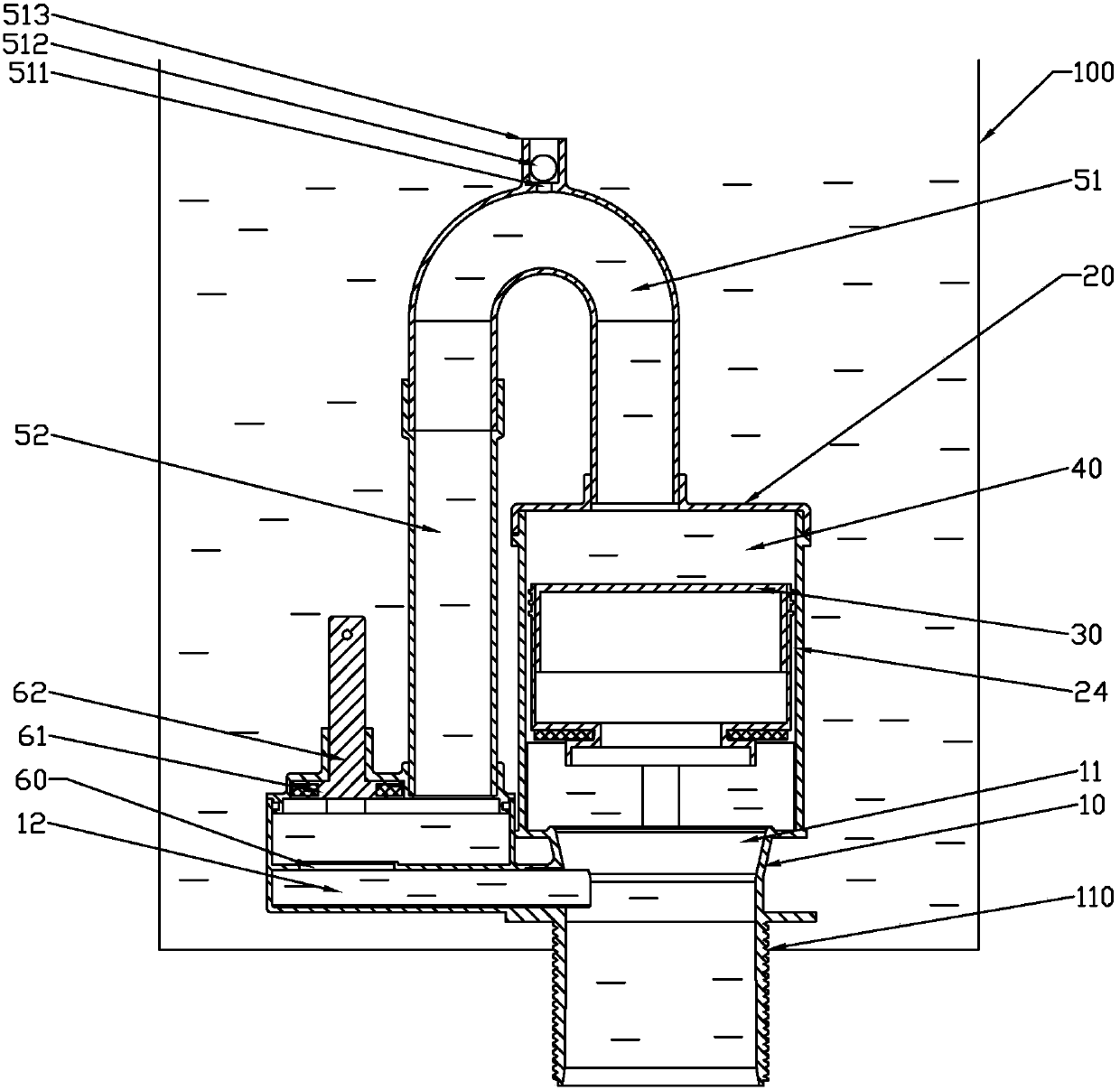
[0058] Such as Figure 5 and Figure 6 As shown, the difference between this embodiment and the first embodiment is that in this embodiment, the valve plate 61 is linked with a float 65 through a connecting rod 62, and the float 65 is fixed upward with a pressing rod 66, which is pressed down when an electric drive mechanism is closed. Press the rod 66 to sink the float 65 and drive the valve plate 61 to seal the flow port 60 through the connecting rod 62. When the electric drive mechanism is opened, release the pressure rod 66 to make the float 65 float up and drive the valve plate 61 to open through the connecting rod 62 The flow port 60, the electric drive mechanism can be a motor, the electric control structure is simple and feasible, and it is convenient to use.

[0059] The rest of the undescribed str...


PUM


Abstract

The invention discloses a drain device for draining water from a water tank by the aid of pressure difference. The drain device comprises a shell, a drain outlet, a floating body, a water storage chamber and a water pumping mechanism. The shell is of a hollow structure, and an opening is formed in the bottom of the hollow structure; the drain outlet is formed in the bottom wall of the water tank; the floating body is movably arranged in the shell and is in seal fit with the drain outlet; the water storage chamber is formed between the inside of the shell and the outside of the floating body and is positioned above the floating body; the water pumping mechanism is communicated with the water storage chamber; water in the water storage chamber can be pumped by the water pumping mechanism, so that up-down pressure difference on the floating body can be changed, the floating body can upwardly float, the drain outlet can be opened, and the water can be drained. The drain device has the advantages that change of the pressure difference on the floating body can be controlled, accordingly, the floating body can float and descend under the control, and the drain device for the water tank can be started and stopped under the control, has low start-stop force values and is simple in structure; the electric control type drain device is easy to design and good in user experience, and electricity can be saved.

Description

technical field [0001] The invention relates to a water tank drainage device utilizing pressure difference to discharge water. Background technique [0002] There are many drainage devices (drainage valves) on the market with various drainage principles and structures. Although most of these drainage devices have relatively reliable functions and stable drainage, they often require a large opening and closing force. For example, the common drain valves open the drain outlet by pulling the water sealing plate in the valve body to realize drainage. Since the water pressure directly acts on the water sealing plate, the force required to lift the water sealing plate is very large, and it is very uncomfortable to use. Convenience, poor user experience, and when the drain valve that requires a large pulling force is designed as an electronic control type, the required motor power is also relatively large, which will shorten the number of times the power supply battery is used, whi...

Claims


Application Information

Patent Timeline
Patent Type & Authority Patents(China)
IPC IPC(8): E03D1/35E03D5/01
CPCE03D1/35E03D5/01E03D2201/30
Inventor 江力
Owner XIAMEN R&T PLUMBING TECH
Why Eureka
Try Eureka