
A steel bar measuring and positioning device and its construction method

A technology for positioning devices and steel bars, which is applied in the direction of measuring devices, mechanical measuring devices, and mechanical devices, etc., can solve problems such as inaccurate positioning of steel bars, and achieve low production costs, strong applicability, and a wide range of operating and user groups.

Active Publication Date: 2017-11-21
TIANYUAN CONSTR GROUP
View PDF8 Cites 0 Cited by
  • Summary
  • Abstract
  • Description
  • Claims
  • Application Information

AI Technical Summary

Problems solved by technology

[0003] The purpose of the present invention is to provide a steel bar measuring and positioning device and its construction method, which can solve the problem of inaccurate positioning of steel bars, thereby ensuring the construction quality of steel bars, reducing the number of scrapped components, and saving prefabrication costs

Method used


Image

  • A steel bar measuring and positioning device and its construction method
  • A steel bar measuring and positioning device and its construction method
  • A steel bar measuring and positioning device and its construction method

Examples


Embodiment 1

[0041] Embodiment one sees Figure 1 to Figure 8 As shown, the steel bar measuring and positioning device is used in the steel bar positioning construction of the wall.

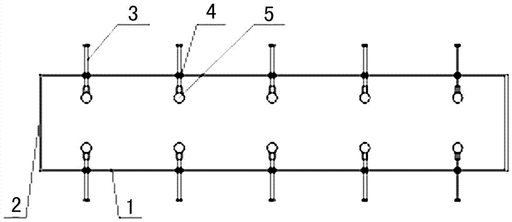
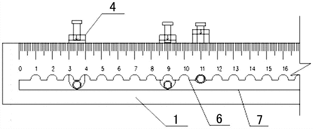
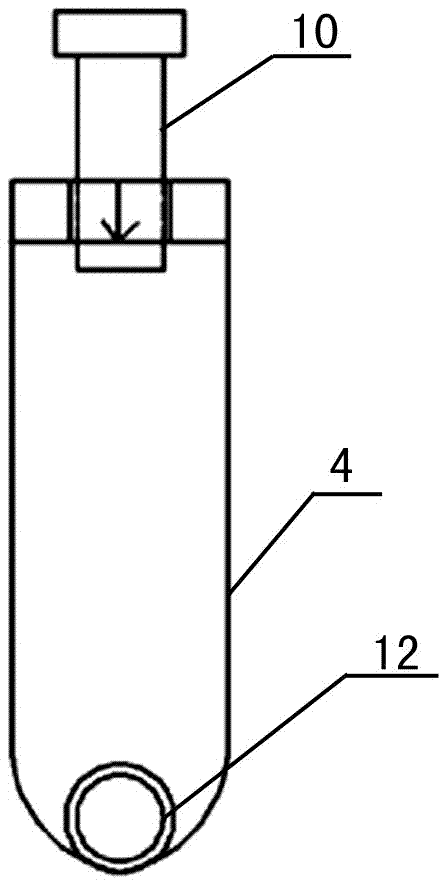
[0042] A steel bar measurement and positioning device, the positioning device is a rectangular frame formed by alternately connecting and enclosing two long-direction positioning rulers 1 and two short-direction positioning rulers 2 in sequence, and the long-direction positioning ruler 1 and the short-direction positioning ruler The ruler 2 is made of light and high-strength steel, and the long-direction positioning ruler 1 and the short-direction positioning ruler 2 are perpendicular to the same plane; wherein the long-direction positioning ruler 1 is movably connected with a mobile clip 4, and the moving The lower end of the clip 4 is horizontally connected with a positioning screw 3 , and the end of the positioning screw 3 is located in a rectangular frame and is connected with a positioning tube 5 .

[0...

Embodiment 2

[0057] Embodiment two see Figure 9 As shown, the difference from the first embodiment is that the steel bar measurement and positioning device is used in the steel bar positioning construction of the prefabricated column. Since the four sides of the prefabricated column have steel bars, the positioning device is sequentially connected by four longitudinal positioning rulers 1 The enclosed rectangular frame does not need to use the short positioning ruler 2, and a positioning rope is flexibly connected between the long positioning rulers on the opposite side, see Figure 2 to Figure 6 As shown, the structure of the longitudinal positioning ruler 1 and its connection relationship with the moving clip 4, the positioning screw 3, the positioning tube 5 and other components are the same as those in the first embodiment.

[0058] The working process of embodiment two is as follows:

[0059] Step 1: According to the diameter and quantity of steel bars at each measurement position i...


PUM


Abstract

Provided are a steel bar measurement positioning device and a construction method thereof. The positioning device is a rectangular frame defined by sequential alternate connection of two long direction positioning scales and two short direction positioning scales or is a rectangular frame defined by sequential connection of four long direction positioning scales. The long direction positioning scales and the short direction positioning scales are perpendicular to the same plane. The long direction positioning scales are movably connected with moving clamping parts, the lower ends of the moving clamping parts are horizontally connected with positioning screws, and the tail ends of the positioning screws are located in the rectangular frame and connected with positioning pipes. According to the steel bar measurement positioning device and the construction method thereof, the problem of steel bar positioning inaccuracy is solved, so that steel bar construction quality is guaranteed, the number of scrapped components is reduced, and the prefabrication cost is reduced.

Description

technical field [0001] The invention relates to the construction field of fabricated reinforced concrete structures, in particular to a steel bar measuring and positioning device and a construction method thereof. Background technique [0002] In the construction process of existing reinforced concrete structures, the positioning of steel bar binding still largely depends on the operator's experience and construction methods. It is difficult to guarantee the accuracy of steel bar positioning, so that there are great hidden dangers in the later construction quality. Especially in the construction process of building industrialized prefabricated buildings, the positioning of the reserved connecting steel bars directly affects the construction progress and construction quality. The connection function of the barrel is lost, so that the overall strength of the structure does not meet the design requirements, there are potential safety hazards, and the maintenance cost is high, w...

Claims


Application Information

Patent Timeline
Patent Type & Authority Patents(China)
IPC IPC(8): E04G21/12G01B5/004
CPCE04G21/12G01B5/004
Inventor 刘军安百平郭玉顺赵桂云崔文涛
Owner TIANYUAN CONSTR GROUP
Learn More