
A cutting head connection structure and modification method

A technology of connecting structure and cutting head, which is used in cutting machinery, earth-moving drilling, elastic coupling, etc., can solve the problems of uneven bearing capacity of spline parts, equipment cannot be put into use, and production efficiency is reduced. The effect of low cost, simple structure and reduced maintenance cost

Active Publication Date: 2018-02-13
GUIZHOU PANJIANG MINING MACHINERY
View PDF5 Cites 0 Cited by
  • Summary
  • Abstract
  • Description
  • Claims
  • Application Information

AI Technical Summary

Problems solved by technology

[0002] The cutting head of the roadheader will be subjected to various forces under working conditions, because the rotation of the cutting head depends on the splines and bearings on the transmission shaft to drive and carry, but the spline position is located at the innermost end of the cutting head, and the connection After being in a cantilever state, due to the harsh working conditions of the cutting head, the bearing capacity of the spline will be uneven, and the local excessive force will cause the spline teeth to bend or break, resulting in damage to the cutting head and high maintenance costs. When the equipment cannot be put into use, the production efficiency is greatly reduced

Method used


Image

  • A cutting head connection structure and modification method
  • A cutting head connection structure and modification method
  • A cutting head connection structure and modification method

Examples


Embodiment 1

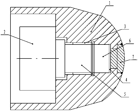
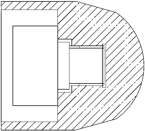
[0025] Embodiment 1: as Figure 1-4 As shown, a cutting head connection structure, including a cutting head 1 and a transmission shaft 2, the cutting head 1 is provided with an internal spline 3, and the inner end of the internal spline 3 is provided with a blind shaft coaxial with the internal spline 3. Hole 4, the transmission shaft 2 is provided with a spline 5, the spline 5 is embedded in the inner spline 3 to mesh with it, and an auxiliary support cylindrical rod 6 coaxial with the transmission shaft 2 is provided at the end, and the auxiliary support cylindrical rod 6 extends into the blind hole 4 and maintain a clearance fit.

[0026] Preferably, the above-mentioned blind hole 4 has a depth of 125-130 mm, and the extension length of the auxiliary support cylindrical rod 6 is 3-5 mm less than the depth of the blind hole 4, which can satisfy the bearing capacity.

[0027] Preferably, the inner diameter of the above-mentioned blind hole 4 and the outer diameter of the aux...

Embodiment 2

[0028] Embodiment 2: as Figure 1-4 Shown, a kind of transformation method of cutting head connection structure, this method comprises the following steps:

[0029] (1) Remove the three pick seats at the end of the cutting head to be modified by gas cutting;

[0030] (2) Find the center of the spherical crown end of the cutting head, and drill a hole with a diameter of 70-80mm;

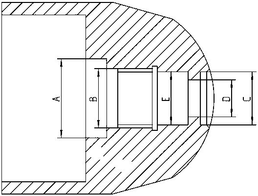
[0031] (3) Install, fix and align the cutting head on the boring machine, taking the cylindrical surface at A∅320 and B∅240 as the benchmark;

[0032] (4) Machining stepped circular holes with sizes C, D and E in the axial direction of the center of the spherical crown end;

[0033] (5) Use the plugging cover 7 to close the stepped hole of and the blind hole formed at the inner end of the spline in the cutting head;

[0034] (6) Weld the three pick holders cut off at the end of the cutting head in step (1) to the cutting position, and align them before welding;

[0035] (7) Set the spline end of t...


PUM


Abstract

The invention discloses a cutter head connecting structure and a reconstruction method thereof. The cutter head connecting structure comprises a cutter head and a transmission shaft, wherein an internal spline is arranged in the cutter head, a blind hole which is coaxial with the internal spline is arranged at the inner end of the internal spline, a spline is arranged on the transmission shaft, is embedded into the internal spline and is engaged with the internal spline, and an auxiliary shoring cylindrical rod which is coaxial with the transmission shaft is arranged at the end part of the spline, extends into the blind hole and is in clearance fit with the blind hole. According to the cutter head connecting structure and the reconstruction method thereof, the radial load bearing of the spline part is achieved through arranging the auxiliary shoring cylindrical rod and the blind hole, the condition that the load bearing of the spline is uneven due to a cantilever is avoided, and the condition that the spline part is uniform in load bearing and stress is ensured, so that the damage to the spline position of equipment is avoided, the service life of the equipment is greatly prolonged, the maintenance is reduced, the maintenance cost is reduced, and the production efficiency is increased greatly; the cutter head connecting structure also has the characteristics of simple structure and low cost.

Description

technical field [0001] The invention relates to a cutting head connection structure and a reconstruction method, belonging to the technical field of roadheaders. Background technique [0002] The cutting head of the roadheader will be subjected to various forces under working conditions, because the rotation of the cutting head depends on the splines and bearings on the transmission shaft to drive and carry, but the spline position is located at the innermost end of the cutting head, and the connection After being in a cantilever state, due to the harsh working conditions of the cutting head, the bearing capacity of the spline will be uneven, and the local excessive force will cause the spline teeth to bend or break, resulting in damage to the cutting head and high maintenance costs. At this time, the equipment cannot be put into use, and the production efficiency is greatly reduced. Contents of the invention [0003] The technical problem to be solved by the present inve...

Claims


Application Information

Patent Timeline
Patent Type & Authority Patents(China)
IPC IPC(8): E21C25/10E21C35/04F16D3/06
CPCE21C25/10E21C35/04F16D3/06
Inventor 谭兵罗书明李俊
Owner GUIZHOU PANJIANG MINING MACHINERY
Learn More