Method and device for starting a drive system of a motor vehicle

A drive system, motor vehicle technology, applied in charging systems, engine components, engine control, etc., can solve complex signal processing, speed reduction and other problems

Active Publication Date: 2016-09-07
MAN NUTZFAHRZEUGE AG
View PDF5 Cites 2 Cited by
  • Summary
  • Abstract
  • Description
  • Claims
  • Application Information

AI Technical Summary

Problems solved by technology

The disadvantage of this solution is that it is particularly adapted to the construction of certain fuel metering systems and requires relatively complex signal p

Method used


Image

  • Method and device for starting a drive system of a motor vehicle
  • Method and device for starting a drive system of a motor vehicle

Examples


Embodiment Construction

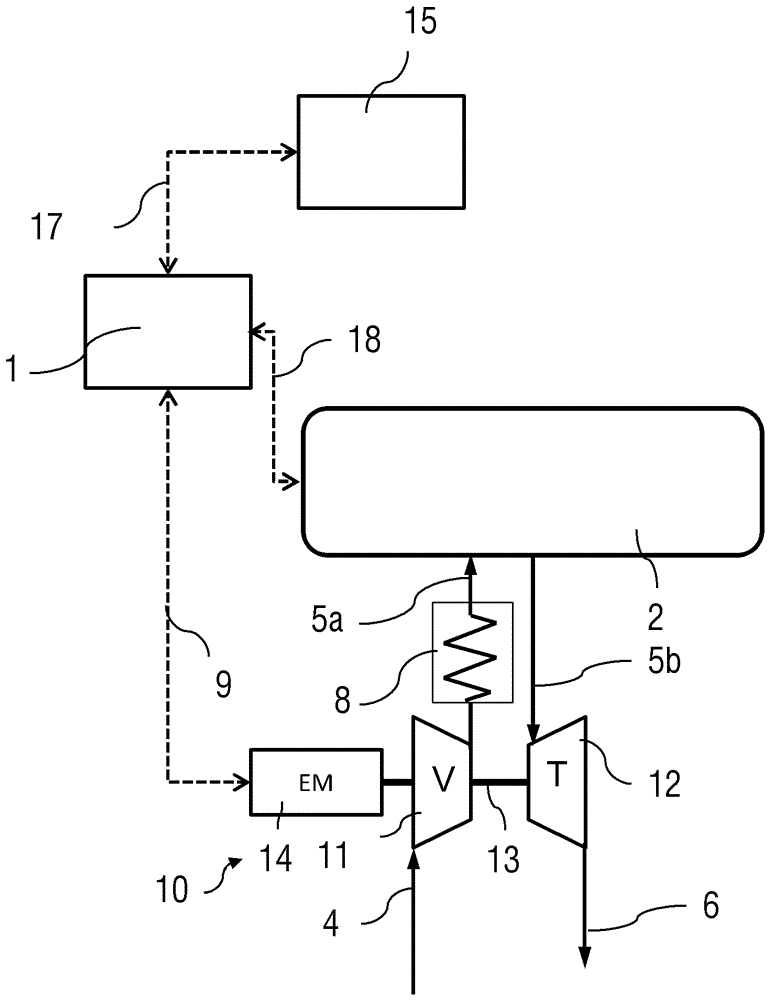
[0048] figure 1 The drive system of a commercial vehicle is shown in the form of a highly schematic block diagram. The drive system comprises a supercharged internal combustion engine 2 , usually a diesel engine, and associated therewith an electrified exhaust-gas turbocharger 10 also referred to hereinafter as ATL. The ATL 10 comprises a turbine 12 driven by the exhaust gases of the internal combustion engine 2 , which are fed to the turbine 12 by means of the exhaust line 5 b. The exhaust gas mixture then flows into the exhaust line 6 via the turbine outlet as far as the exhaust pipe and thus passes through an exhaust aftertreatment device (not shown), if present.

[0049] The turbine 12 is connected to the compressor 12 by means of a shaft 13 . Fresh air is fed to the compressor 11 by means of the compressor inlet line 4 . The compressor 11 compresses the charge air to be fed to the internal combustion engine 2 and thus increases the power of the internal combustion engi...


PUM


Abstract

The invention relates to a method and device for starting a drive system of a motor vehicle, specifically relates to a method for starting the drive system of the motor vehicle with an internal combustion engine, and especially to a method used for overspeed protection of the drive system. The invention also relates to a device for performing such method. According to the invention, when at least one starting condition used for starting the overspeed protection of the drive system is met, the overspeed protection is started, and the electric generator mold of the electrification exhaust turbine supercharger is started.

Description

technical field [0001] The invention relates to a method for starting a drive system of a motor vehicle with an internal combustion engine, in particular such a method for overspeed protection of the drive system. The invention also relates to a device arranged to carry out such a method. Background technique [0002] It is known from practice that under certain operating conditions of a motor vehicle, the thermodynamic coupling of the engine and the exhaust-gas turbocharger can lead to critical states of the exhaust-gas turbocharger, e.g. in hot exhaust and high In overspeed in the case of exhaust gas mass flow. When such an overspeed occurs, there is a risk of damage to the rotor of the exhaust-gas turbocharger, to the charge air system and in some cases to the internal combustion engine due to the excessive charge pressure and thus the peak combustion pressure. [0003] It is known from the prior art to detect such critical operating states by means of engine sensors (e...

Claims


Application Information

Patent Timeline
IPC IPC(8): F02D41/22
CPCF02D41/22F02D41/221F02D2041/227F02D2200/0406F02D41/1446F02B37/10F02B37/14F02B37/24F02B39/10F02D31/006F02D41/0007F02M26/49Y02T10/12
Inventor A.帕彭海默A.佐默曼
Owner MAN NUTZFAHRZEUGE AG
Why Eureka
Try Eureka