
Wireless intelligent emergency illumination lamp and wireless intelligent emergency illumination system

A technology of emergency lighting and lighting lamps, which is applied in the direction of lighting devices, lighting auxiliary devices, lighting and heating equipment, etc., can solve the problems of short service life, high cost, and the inability to realize the real-time working status of remote control emergency lighting lamps, etc., to reduce The effect of reducing construction costs, improving service life, and ensuring smooth communication

Inactive Publication Date: 2016-09-07
SHENZHEN GATEWAY INTELLIGENT TECH
View PDF7 Cites 7 Cited by
  • Summary
  • Abstract
  • Description
  • Claims
  • Application Information

AI Technical Summary

Problems solved by technology

The existing emergency lights in each corridor usually communicate through wired methods when transmitting data, which not only requires the laying of a large number of communication lines, making the construction process complicated and high in cost, but also the wired communication lines are easily damaged in the event of a fire or other disaster. , making its communication function impaired
On the other hand, the performance parameters of the existing emergency lighting only meet the requirements of the relevant national regulations, and there are problems such as short service life, small irradiation range and single installation method.
In addition, the existing emergency lighting system can usually only realize a single function of lighting, and cannot realize remote control and timely grasp the real-time working status of each emergency lighting.

Method used


Image

  • Wireless intelligent emergency illumination lamp and wireless intelligent emergency illumination system
  • Wireless intelligent emergency illumination lamp and wireless intelligent emergency illumination system
  • Wireless intelligent emergency illumination lamp and wireless intelligent emergency illumination system

Examples


Embodiment Construction

[0029] The following examples are further explanations and supplements to the present invention, and do not constitute any limitation to the present invention.

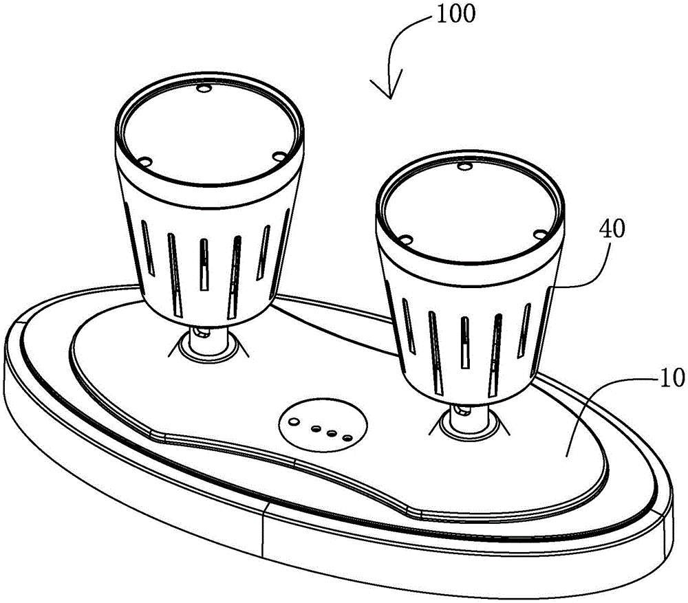
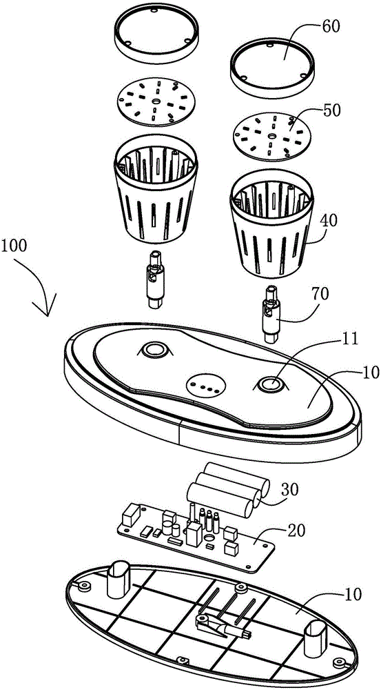
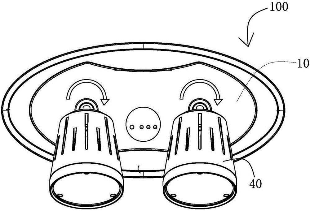
[0030] refer to figure 1 , figure 2 , Figure 5 and Image 6 , The wireless intelligent emergency lighting 100 of the present invention includes a base 10 , a circuit board 20 , a spare battery 30 , a lamp holder 40 , an LED lamp board 50 , a lampshade 60 and a universal joint 70 . The wireless intelligent emergency lighting 100 is installed in the corridor of the floor of the building. It can be installed on the wall of the corridor or on the ceiling of the corridor. When a disaster such as a fire occurs, the wireless intelligent emergency lighting 100 can for emergency lighting.

[0031] Such as figure 1 , figure 2 As shown, the base 10 has an elliptical structure, which is formed by joining the upper cover and the lower cover through clamping or threaded connection. The lower cover of the base 10 is provid...


PUM


Abstract

The invention provides a wireless intelligent emergency illumination lamp provided with a base. A circuit board and a standby battery are arranged in the base. A rotational lamp holder is arranged on the base, the lamp holder can rotate around the horizontal axis and / or vertical axis of the base, an LED lamp plate and a lampshade connected to the top end of the lamp holder are arranged in the lamp holder, the circuit board is electrically connected with an external power source and the standby battery, the LED lamp plate is electrically connected with the circuit board, and the circuit board is provided with a wireless communication module. The invention further discloses a wireless intelligent emergency illumination system. The system comprises emergency illumination lamps, a wireless data acquisition device, a router and a host. The emergency illumination lamps can send real-time work states of the emergency illumination lamps to the host by means of the wireless communication module. The wireless intelligent emergency illumination lamp has the advantages that the construction process is simple, construction cost is low, the cooling effect is good, and service life is long.

Description

【Technical field】 [0001] The invention relates to fire-fighting emergency lighting equipment, in particular to a wireless intelligent emergency lighting lamp and a wireless intelligent emergency lighting system with good heat dissipation effect, no need to lay communication lines and self-organizing network. 【Background technique】 [0002] As a commonly used fire-fighting facility, emergency lights are widely distributed in the corridors of buildings to provide lighting for trapped people in emergency situations. The existing emergency lights in each corridor usually communicate through wired methods when transmitting data, which not only requires the laying of a large number of communication lines, making the construction process complicated and high in cost, but also the wired communication lines are easily damaged in the event of a fire or other disaster. , making its communication function impaired. On the other hand, the performance parameters of existing emergency lig...

Claims


Application Information

Patent Timeline
IPC IPC(8): F21S9/02F21V17/10F21V21/29F21V23/00F21V29/70F21V29/87H05B33/08F21Y115/10H05B44/00
CPCF21S9/022F21V17/02F21V21/29F21V23/00F21V29/70F21V29/87H05B45/50H05B45/00
Inventor 欧阳迁陈张生邱家祥
Owner SHENZHEN GATEWAY INTELLIGENT TECH
Learn More