Infrared focal plane detector blind pixel correction method

An infrared focal plane and blind element correction technology, applied in the field of blind element correction, can solve the problems of blind element location consumption of storage resources, unfavorable mass production and use, etc.

Inactive Publication Date: 2016-09-07
JING LIN CHENGDU SCI & TECH
View PDF4 Cites 8 Cited by
  • Summary
  • Abstract
  • Description
  • Claims
  • Application Information

AI Technical Summary

Problems solved by technology

Judging from the current literature, the existing blind pixel detection and compensation algorithms at home and abroad are mainly the blind pixel correction calibration method. This method calibrates the position information of the blind pixel, and then corrects the blind pixel by the surrounding average value. This method can a...

Method used


Image

  • Infrared focal plane detector blind pixel correction method

Examples


Embodiment Construction

[0013] The technical solution of the present invention will be further described in detail below in conjunction with the accompanying drawings, but the protection scope of the present invention is not limited to the following description.

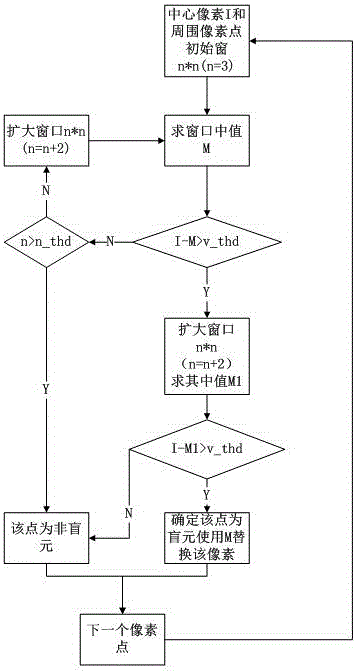
[0014] like figure 1 As shown, a blind element correction method of an infrared focal plane detector comprises the following steps:

[0015] S1: Find the initial window n*n (n=3) of the center pixel I and the surrounding pixels; / / find the initial window n*n (n=3) composed of the image pixel I as the center and the surrounding pixels;

[0016] S2: Find the median value M of the window, and judge whether I-M is greater than the preset threshold v_thd. If I-M>v_thd is not established, continue to judge whether n is greater than the preset threshold n_thd. If n>n_thd is established, judge that the point is a non-blind element, and enter The next pixel; if n>n_thd is not established, expand the window n*n (n=n+2), and continue to find the medi...


PUM


Abstract

The invention discloses an infrared focal plane detector blind pixel correction method. The method comprises the following steps: calculating an image pixel I, which serves as a center, and an initial window n*n(n=3) formed by surrounding pixels; calculating a window median M, and judging whether the I-M is larger than a preset threshold value v_thd; if I-M>v_thd fails, judging whether n is larger than a preset threshold value n_thd, and if n >n_thd, judging the point is a non-blind pixel, and turning to a next pixel point; if n >n_thd fails, enlarging the window n*n(n=n+2), and calculating the window median M; if I-M> v_thd, skipping to the next step; enlarging the window n*n(n=n+2), and calculating the window median M1; and judging whether the I-M1 is larger than the v_thd, if not, judging the point is a non-blind pixel, and if so, judging the point is a blind pixel, using M to replace the pixel and turning to the next pixel point. The basic idea is a variable window blind pixel elimination method; and the method, based on characteristics of blind pixels in the practical application, does not need to store the blind pixel information, and can finish correction of all blind pixels without iteration for any qualified detector at any time.

Description

technical field [0001] The invention relates to a blind element correction method, in particular to a blind element correction method for an infrared focal plane detector. Background technique [0002] The uncooled infrared focal plane array is a large area detector. Due to the inconsistency of the semiconductor material used to make the device, mask error, defect, process, etc., the infrared focal plane detector has inevitable non-uniformity and blind elements. If these problems are ignored, the imaging image has a poor signal-to-noise ratio. These blind pixel points appear in the image as their gray value changes slowly, which cannot correctly reflect the change of the scene. For the definition of blind element, it mainly takes the degree of response of the device to black body radiation as a quantitative index. Judging from the current literature, the existing blind pixel detection and compensation algorithms at home and abroad are mainly the blind pixel correction cali...

Claims


Application Information

Patent Timeline
IPC IPC(8): G01J5/00
CPCG01J5/00G01J5/80
Inventor 谢雪平曾衡东章睿董涛
Owner JING LIN CHENGDU SCI & TECH
Why Eureka
Try Eureka