Magnetic coupling feeding based circularly polarized antenna

A circularly polarized antenna and magnetic coupling technology, applied in the direction of antenna, electrical components, radiating element structure, etc., can solve the problem of increasing the size of the antenna, the difficulty of getting favored by the helical antenna, and the low polarization sensitivity of the target signal of the circularly polarized antenna. problem, to achieve the effect of excellent circular polarization performance and small size

Inactive Publication Date: 2016-09-07
成都雷电微力科技股份有限公司
View PDF3 Cites 7 Cited by
  • Summary
  • Abstract
  • Description
  • Claims
  • Application Information

AI Technical Summary

Problems solved by technology

[0002] Circularly polarized antennas are widely used in various communication products because of their low polarization sensitivity to target signals. Currently, commonly used circularly polarized antennas include helical antennas, microstrip double-fed antennas, microstrip single-fed antennas, coupled Antennas, etc., but for broadband circularly polarized antenna arrays, the large size of the helical antenna and the narrowband characteristics of microstrip single-feed / double-feed are difficult to gain favor. A better selection scheme for antennas. Most of these antennas are based on electric field coupling feeding. The characteristic of electric field coupling feeding is that the feeding point is not on the geometric axis of the antenna, which will cause a certain gap between the phase center of the antenna and the feeding point. distance, thereby additionally increasing the size of the antenna

Method used


Image

  • Magnetic coupling feeding based circularly polarized antenna
  • Magnetic coupling feeding based circularly polarized antenna
  • Magnetic coupling feeding based circularly polarized antenna

Examples


Embodiment Construction

[0030] The present invention will be further described in detail below in combination with specific embodiments. However, it should not be understood that the scope of the above subject matter of the present invention is limited to the following embodiments, and all technologies realized based on the content of the present invention belong to the scope of the present invention.

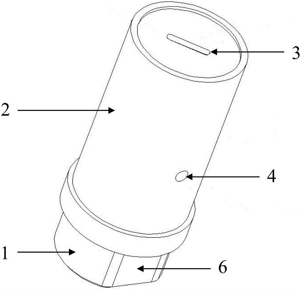
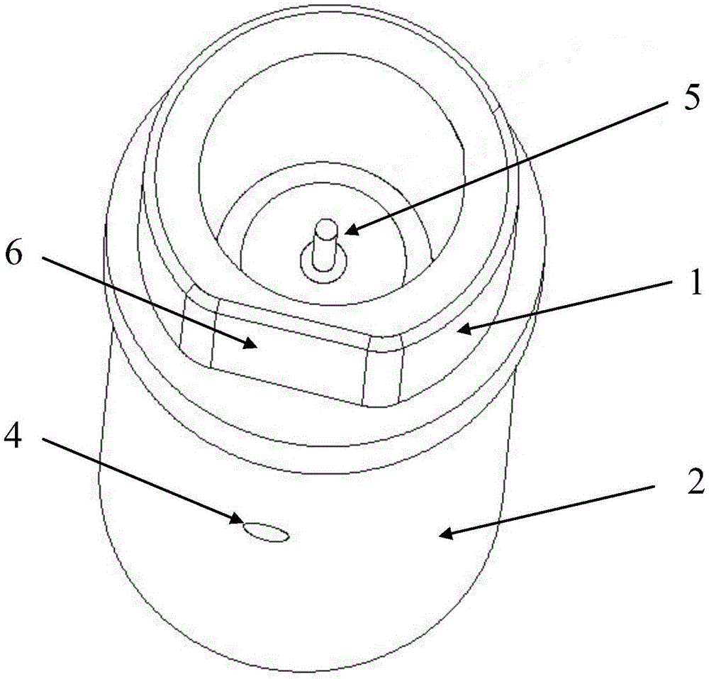
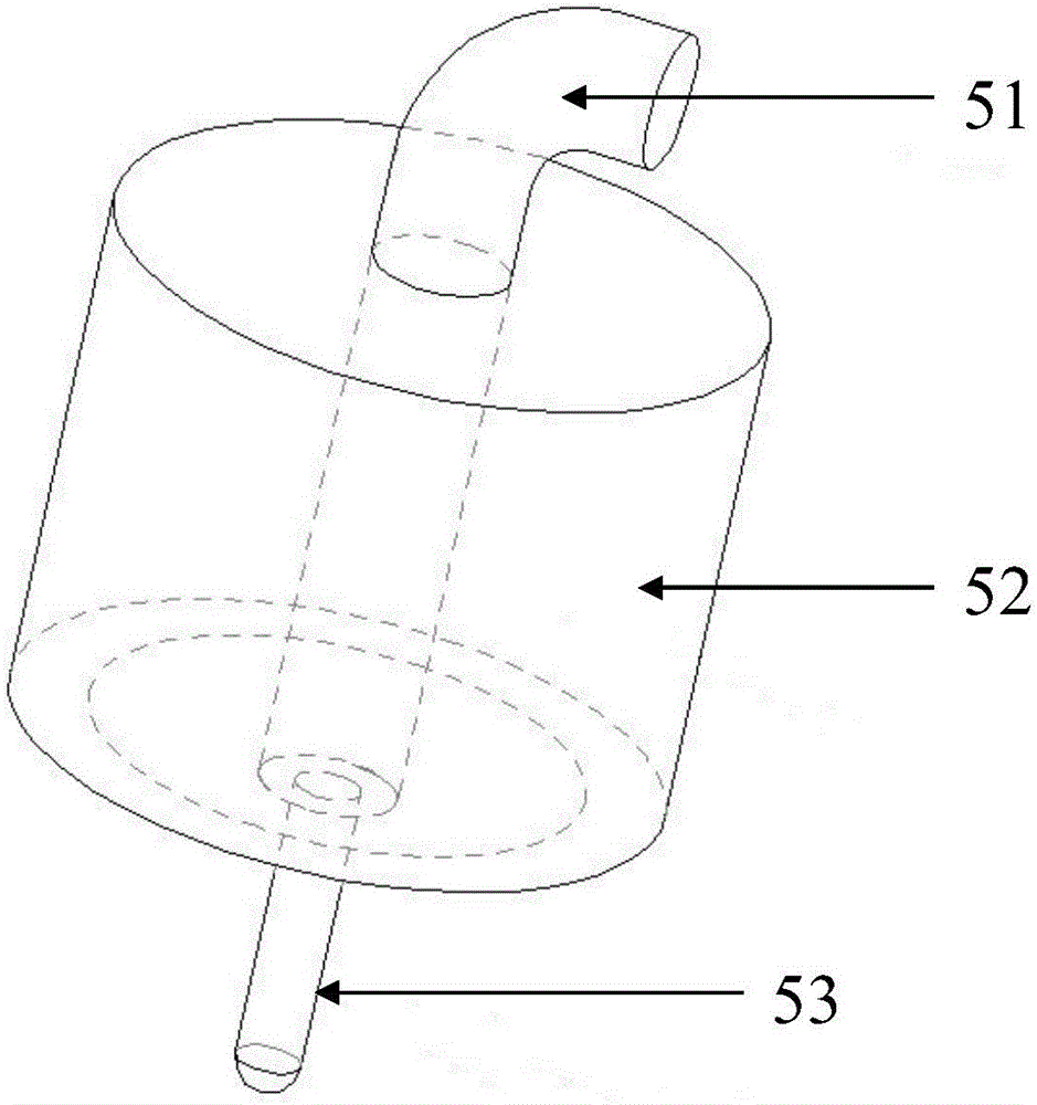
[0031] combine figure 1 , figure 2 , image 3 and Figure 4 The structural representations of the radiating end, feeding end, feeding part and antenna housing of the antenna of the present invention shown respectively; 5 and a polarized metal sheet 3, the feeding part 5 is set in the feed-in end 1 of the antenna case, and the polarized metal sheet 3 is set in the radiating end 2 of the antenna case.

[0032] Wherein, the radiation end 2 of the antenna housing has a rectangular waveguide cavity 22 and a circular waveguide cavity 21 , and the polarized metal sheet 3 is located on the axis of the ci...


PUM


Abstract

The invention discloses a magnetic coupling feeding based circularly polarized antenna. The circularly polarized antenna comprises an antenna shell, a feeding part and a polarized metal sheet, wherein the feeding part is arranged at the feeding end of the antenna shell; the polarized metal sheet is arranged at the radiating end of the antenna shell; a rectangular waveguide cavity and a circular waveguide cavity are formed in the radiating end of the antenna shell; the polarized metal sheet is arranged on the axial line of the circular waveguide cavity; a signal fed by a signal feeding probe of the feeding part is transmitted to the rectangular waveguide cavity through a magnetic coupling curved needle for converting a TEM mode into a TE10 mode of the rectangular waveguide; then the signal passes through the circular waveguide cavity for converting the TE10 mode into a TE11 mode; and finally, the TE11 mode is subjected to polarization adjustment by the polarized metal sheet to radiate circularly polarized electromagnetic wave. Therefore, the feeding point can be set on the geometric axial line of the antenna; and meanwhile, the antenna has a relatively small size and relatively high circularly polarized performance.

Description

technical field [0001] The invention relates to the technical field of antennas, in particular to a circularly polarized antenna based on magnetic coupling feeding. Background technique [0002] Circularly polarized antennas are widely used in various communication products because of their low polarization sensitivity to target signals. Currently, commonly used circularly polarized antennas include helical antennas, microstrip double-fed antennas, microstrip single-fed antennas, coupled Antennas, etc., but for broadband circularly polarized antenna arrays, the large size of the helical antenna and the narrowband characteristics of microstrip single-feed / double-feed are difficult to gain favor. A better selection scheme for antennas. Most of these antennas are based on electric field coupling feeding. The characteristic of electric field coupling feeding is that the feeding point is not on the geometric axis of the antenna, which will cause a certain gap between the phase ce...

Claims


Application Information

Patent Timeline
Patent Type & Authority Applications(China)
IPC IPC(8): H01Q1/36H01Q1/42H01Q15/24
CPCH01Q1/36H01Q1/42H01Q15/24
Inventor 张成丁卓富管玉静
Owner 成都雷电微力科技股份有限公司
Why Eureka
Try Eureka