Magnetic-driven linear reciprocating yarn guide device and application method thereof
A technology of linear reciprocating and yarn guiding device, which is applied in the directions of transportation and packaging, transportation of filamentous materials, processing of thin materials, etc. and other problems, to achieve the effect of high precision control, avoidance of internal friction, and low internal friction
- Summary
- Abstract
- Description
- Claims
- Application Information
AI Technical Summary
Problems solved by technology
Method used
Image
Examples
Embodiment 1
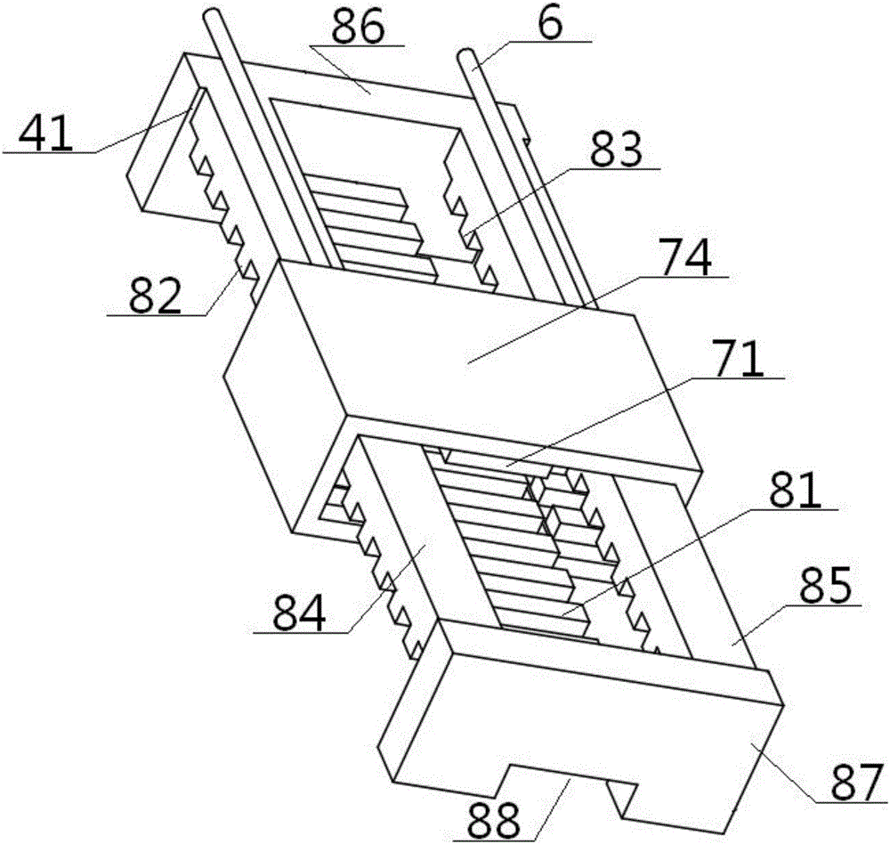
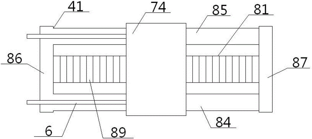
[0051] see Figure 1 to Figure 6 , a linear reciprocating yarn guide device driven by magnetic force, comprising a friction roller 1, a yarn reel 2 and a yarn guide system 4, the top surface of the friction roller 1 is in contact with the bottom surface of the yarn reel 2, the friction roller 1, The yarn bobbin 2 is frictionally driven and matched, the circumferential surface of the yarn bobbin 2 is wound with the yarn 3, the other end of the yarn 3 is connected with one end of the yarn guide rod 6 after passing through the yarn guide nozzle 5, and the other end of the yarn guide rod 6 It is connected with the front plate surface of the slider top plate 74 in the yarn guide system 4; the yarn guide system 4 includes a slider unit 7 and a slide rail unit 8 passing through it, and the slider unit 7 and the slide rail unit 8 are in the Sliding fit on a straight line;
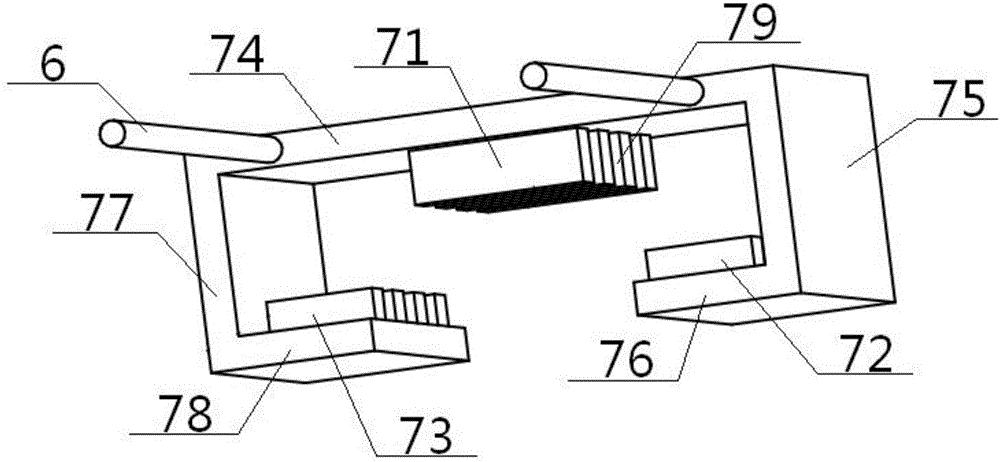
[0052] The slider unit 7 includes a top thrust winding 71, a left suspension winding 72, a right suspension win...
Embodiment 2
[0057] Basic content is the same as embodiment 1, the difference is:
[0058]Under the action of the thrust, the slider top plate 74 runs linearly along the initial direction to the predetermined position, then changes the direction of the three-phase current to change the direction of the thrust force, so that the slider top plate 74 returns along the original route, and cycles in turn to realize the slider top plate 74 reciprocating motion in a linear direction.
Embodiment 3
[0060] Basic content is the same as embodiment 1, the difference is:
[0061] The slider unit 7 also includes a left vertical plate 75, a left supporting plate 76, a right vertical plate 77 and a right supporting plate 78, the top of the left vertical plate 75 is vertically connected with the left end of the slider top plate 74, and the left vertical plate 75 The bottom of the bottom is vertically connected with the outer end of the left supporting plate 76, the inner end of the left supporting plate 76 and the inner end of the right supporting plate 78 are directly arranged, the outer end of the right supporting plate 78 is vertically connected with the bottom of the right vertical plate 77, and the right vertical plate 77 is vertically connected. The top of the plate 77 is vertically connected with the right end of the slider top plate 74, the top thrust winding 71 is located between the inner end of the left supporting plate 76 and the inner end of the right supporting plate...
PUM
 Abstract
Description
Claims
Application Information
 - R&D
- Intellectual Property
- Life Sciences
- Materials
- Tech Scout
- Unparalleled Data Quality
- Higher Quality Content
- 60% Fewer Hallucinations
Browse by: Latest US Patents, China's latest patents, Technical Efficacy Thesaurus, Application Domain, Technology Topic, Popular Technical Reports.
© 2025 PatSnap. All rights reserved.Legal|Privacy policy|Modern Slavery Act Transparency Statement|Sitemap|About US| Contact US: help@patsnap.com


