Magnetic control power machine

A power machine and power output shaft technology, applied in electromechanical devices, electrical components, DC arc interrupters, etc., can solve the problems of narrow thinking, inability to combine, and the design cannot withstand scientific scrutiny, so as to overcome internal friction and save manufacturing materials. , the effect of significant energy saving effect

Inactive Publication Date: 2009-09-23
程序
View PDF1 Cites 0 Cited by
  • Summary
  • Abstract
  • Description
  • Claims
  • Application Information

AI Technical Summary

Problems solved by technology

But in reality, I haven't seen anything practical. Why? Personally, I think the reasons are as follows: first, it violates the laws of natural science, and the proposed design cannot withstand scientific scrutiny; second, the thinking is narrow, and the focus is on unrestricted power output, and finally turns into a failed perpetual motion machine; third. 1. Not tracking the development of science and technology, emphasizing forward-thinking innovation, lacking a practical foundation; 4. Not combining innovative thinking with practical application to embark on the right path

Method used


Image

  • Magnetic control power machine
  • Magnetic control power machine

Examples


Embodiment 1

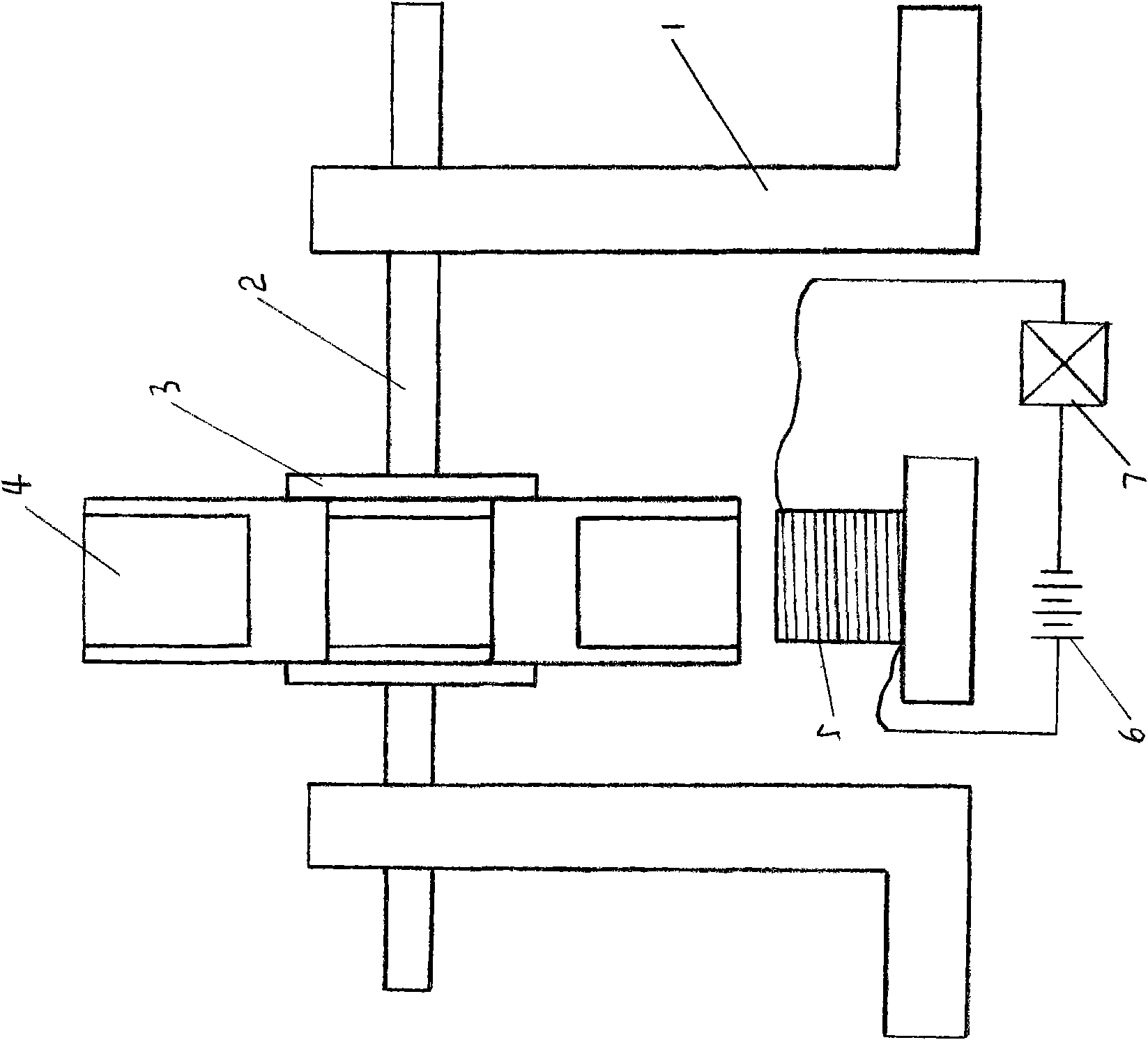
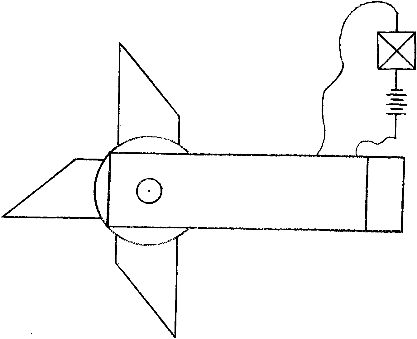
[0030] Embodiment 1: The structure of the magnet braking power machine is that the base 1 supports the power output shaft 2, and the runner 3 is fixed on the shaft, and four permanent magnets 4 are installed on the four tops of the runner 3, and are installed in cooperation with the permanent magnets. A magnetizing component 5 is provided with a coil corresponding to the permanent magnet 4 on the periphery of the runner 3 .

[0031] The outer end face of the permanent magnet 4 is a permanent magnet with a slope of 45 degrees.

[0032] The magnetizing component 5 is composed of an electromagnet, a controller 7 and a power supply 6 .

[0033] Described controller 7 is made of electronic chip.

[0034] The electronic chips in the controller 7 include a speed control chip, a power switch control chip, and a time control chip.

[0035] When in use, when the permanent magnet is close to the electromagnet, the control chip is powered on, so that the electromagnet generates a magnet...

Embodiment 2

[0036] Embodiment 2: The structure of the magnetic braking power machine is that the base 1 supports the power output shaft 2, and the runner 3 is fixed on the shaft, and eight permanent magnets 4 are installed on the eight tops of the runner 3, and are installed in cooperation with the permanent magnets. A magnetizing component 5 is fixed with an inertial flywheel on the power output shaft 2, and the inertial flywheel is connected with the starter.

[0037] The outer end face of the permanent magnet 4 is a permanent magnet with a slope of 25 degrees.

[0038] The magnetizing component 5 is composed of an electromagnet, a controller 7 and a power supply 6 .

[0039] Described controller 7 is made of electronic chip.

[0040] The electronic chips in the controller 7 include a speed control chip, a power switch control chip, and a time control chip.

[0041] When in use, when the permanent magnet is close to the electromagnet, the control chip is powered on, so that the electr...


PUM


Abstract

The invention relates to a magnetic control power machine. The magnetic control power machine belongs to an electric machine or an energy source power output machine. The magnetic control power machine solves the problems of energy conservation and new energy resource development of motors. The technical proposal comprises that: a power output shaft 2 is supported by a machine seat 1; a rotating wheel 3 is fixed on the shaft; a permanent magnet 4 is arranged at the top end of the rotating wheel 3; and a magnetic control part 5 is arranged to match with the permanent magnet. The product can be used for supplying power or supplying energy output power.

Description

1. Technical field [0001] The invention relates to a machine for providing power, in particular to a magnetizing power machine. 2. Background technology [0002] Since the existence of human beings, early human power mainly came from human power, animal power, and water power. After Watt perfected the steam engine in 1790, a new practical heat source power machine was produced. Then humans invented the internal combustion engine, gas turbine, electric motor, etc., making the power machine a working machine. However, with the development of human beings, the gradual consumption of the earth's resources, and the exposed environmental degradation problems, people have to reflect on their behavior, which has destroyed the thinking and action of pursuing technological creation, innovation, and solving the problems they face. [0003] Can you create a new type of power machine that consumes less resources than the existing power machine? (This is an energy-saving idea); Can you...

Claims


Application Information

Patent Timeline
Patent Type & Authority Applications(China)
IPC IPC(8): H02K25/00H02K53/00
Inventor 程序程涛
Owner 程序
Why Eureka
Try Eureka