
Flexible anchor rod

An anchor rod and flexible technology, applied in the installation of anchor rods, mining equipment, earth-moving drilling, etc., can solve the problems of high cost, inability to tighten nuts, low compressive strength, etc., and achieve convenient installation and construction, small exposed length, and rod body. high intensity effect

Inactive Publication Date: 2016-09-14
于守东
View PDF9 Cites 0 Cited by
  • Summary
  • Abstract
  • Description
  • Claims
  • Application Information

AI Technical Summary

Problems solved by technology

[0002] The anchor products used in the existing coal mine roadway support are generally made of threaded steel bars without longitudinal reinforcement, which have disadvantages such as low compressive strength, heavy weight, inability to bend, and high cost. However, flexible anchors made of steel strands Although the rod has the advantages of high strength, light weight, bendability, and unlimited length, it will twist when the nut is attached because the rod is flexible, making the nut unable to be tightened, and the rod cannot generate a certain pre-tightening force. Timely and effective support for the roadway, which limits the popularization and use of flexible anchors

Method used


Image

  • Flexible anchor rod
  • Flexible anchor rod
  • Flexible anchor rod

Examples


Embodiment 1

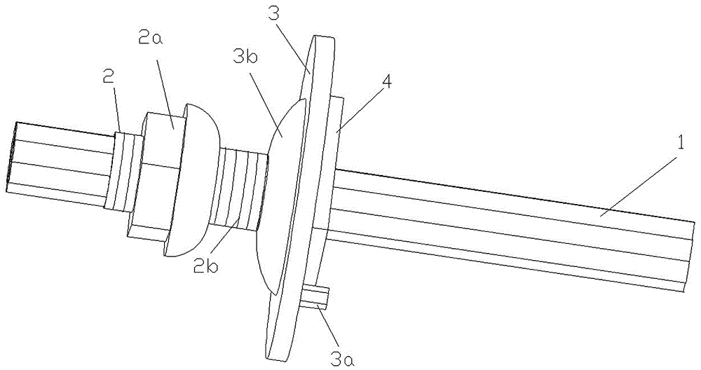
[0016] Such as figure 1 , 2 As shown, a flexible anchor rod is characterized in that: it includes a steel strand 1, on the steel strand 1, the sleeve 2 is fixed on the steel strand 1 by hydraulic pressing with an extrusion spring not shown in the figure. 1 on. The extruded spring is a steel cylindrical spring with a triangular cross-section.

[0017] Thread 2b is provided on the outer wall of the casing 2, and a spherical crown self-aligning nut 2a corresponding to the thread is sleeved on the casing 2, and a combination of ordinary nuts and spherical washers can also be used to replace the spherical crown self-aligning nut 2a .

[0018] A tray 3 is provided, and an upwardly protruding circular arch 3b is arranged on the tray 3. A through hole corresponding to the sleeve pipe 2 is provided at the center of the circular arch 3b. On the lower surface of the tray 3, there is also a vertical There is a columnar pin 3a.

[0019] The tray 3 is threaded on the steel strand 1 on ...

Embodiment 2

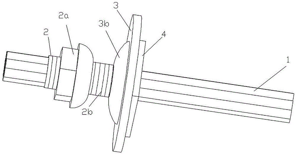
[0026] Such as figure 2 , 3 As shown, a flexible anchor rod is characterized in that: it includes a steel strand 1, on the steel strand 1, the sleeve 2 is fixed on the steel strand 1 by hydraulic pressing with an extrusion spring not shown in the figure. 1 on. The extruded spring is a steel cylindrical spring with a triangular cross-section.

[0027] Thread 2b is provided on the outer wall of the casing 2, and a spherical crown self-aligning nut 2a corresponding to the thread is sleeved on the casing 2, and a combination of ordinary nuts and spherical washers can also be used to replace the spherical crown self-aligning nut 2a .

[0028] A tray 3 is provided, and an upwardly protruding circular arch 3b is provided on the tray 3, and a through hole corresponding to the sleeve 2 is provided at the center of the circular arch 3b.

[0029] The tray 3 is threaded on the steel strand 1 on the spherical side of the spherical crown self-aligning nut 2a, so that the top end of the...


PUM


Abstract

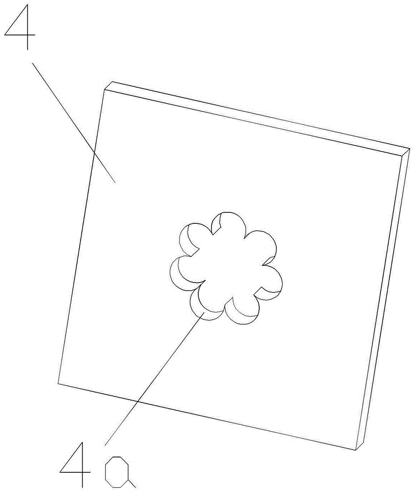
The invention provides a flexible anchor rod. The flexible anchor rod is characterized by comprising a steel strand (1); the steel strand (1) is sleeved with a sleeve (2), a correspondingly matched nut (2a) is further arranged on the sleeve (2), a tray (3) is arranged at the position, at one side of the sleeve (2), of the steel strand (1) in a penetrating mode, and a locking plate (4) is arranged on one side of the tray (3). The flexible anchor rod has the advantages that the structure is simple, use is convenient, self strength is high, bearing performance is high, a rod body does not ratate when the nut is screwed down, locking is reliable, and slipping is avoided.

Description

Technical field: [0001] The invention designs a bolt used for supporting a coal mine roadway, specifically a flexible bolt. Background technique: [0002] The anchor products used in the existing coal mine roadway support are generally made of threaded steel bars without longitudinal reinforcement, which have disadvantages such as low compressive strength, heavy weight, inability to bend, and high cost. However, flexible anchors made of steel strands Although the rod has the advantages of high strength, light weight, bendability, and unlimited length, it will twist when the nut is attached because the rod is flexible, making the nut unable to be tightened, and the rod cannot generate a certain pre-tightening force. Timely and effective support is produced for the roadway, which limits the popularization and use of flexible anchor rods. Invention content: [0003] The purpose of the present invention is to overcome the deficiencies in the prior art and provide a flexible a...

Claims


Application Information

Patent Timeline
IPC IPC(8): E21D21/00
CPCE21D21/0033E21D21/004
Inventor 于守东魏玉东于泽吴魏红
Owner 于守东
Learn More