Rotary compressor

A technology of rotary compressors and compression mechanisms, which is applied in the direction of rotary piston machines, rotary piston pumps, mechanical equipment, etc., which can solve problems such as deterioration of bearing lubrication conditions, decreased rigidity of countershafts, and increased deflection, and achieves deflection Effects of reduced curvature, increased rigidity, and improved efficiency

Inactive Publication Date: 2016-09-14
MITSUBISHI ELECTRIC CORP
View PDF6 Cites 0 Cited by
  • Summary
  • Abstract
  • Description
  • Claims
  • Application Information

AI Technical Summary

Problems solved by technology

For this reason, if the outer diameter of the sub-shaft having the oil supply hole inside is reduced as described above, there is a concern that the rigidity of the sub-shaft decreases, and the sub-shaft may suffer from the gas load when the refrigerant gas is compressed in the compression chamber. The amount of deflection increases, the lubrication condition of the bearing deteriorates, the shaft and the bearing are sintered during the operation of the compressor, and the operation of the compressor stops and cannot be restarted

Method used


Image

  • Rotary compressor
  • Rotary compressor
  • Rotary compressor

Examples


Embodiment approach 1

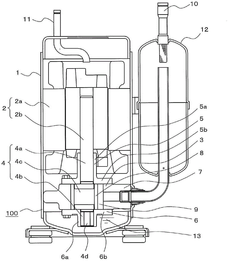
[0026] figure 1 It is a schematic configuration diagram showing the rotary compressor 100 according to Embodiment 1 of the present invention.

[0027] In Embodiment 1, as the rotary compressor 100 , a vertical rotary hermetic electric compressor is shown as an example. The rotary compressor 100 is used in a refrigeration cycle of an air conditioner or the like.

[0028] Such as figure 1 As shown, in the rotary compressor 100 , a compression mechanism unit 3 for compressing a refrigerant is disposed at the lower portion and an electric motor (motor unit) 2 for driving the compression mechanism unit 3 is disposed at the upper portion in a sealed container 1 with a high-pressure atmosphere. The electric motor 2 has a stator 2 a and a rotor 2 b, and is configured to rotate a crankshaft 4 which is a rotating shaft fixed to the rotor 2 b, and to drive the compression mechanism unit 3 by the crankshaft 4 .

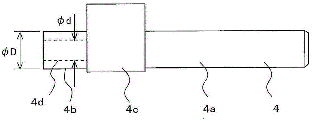
[0029] The crankshaft 4 has: a main shaft 4a fixed to the rotor 2b of the...

Embodiment approach 2

[0060] Figure 5 It is a refrigerant circuit diagram showing an example of the refrigeration cycle apparatus 200 to which the rotary compressor 100 according to Embodiment 2 of the present invention is applied.

[0061] Figure 5 The illustrated refrigeration cycle device 200 forms a refrigeration cycle circuit in which a rotary compressor 100 , a condenser 201 , an expansion valve 202 , and an evaporator 203 are connected by refrigerant piping. Furthermore, the refrigerant flowing out of the evaporator 203 is sucked into the rotary compressor 100 and compressed to become high temperature and high pressure. The high-temperature and high-pressure refrigerant is condensed in the condenser 201 to become a liquid. The liquid refrigerant decompresses and expands in the expansion valve 202 to become a low-temperature and low-pressure gas-liquid two-phase state, and the gas-liquid two-phase refrigerant exchanges heat in the evaporator 203 .

[0062] The rotary compressor 100 can b...


PUM

PropertyMeasurementUnit
Diameteraaaaaaaaaa
Longitudinal modulus of elasticityaaaaaaaaaa
The inside diameter ofaaaaaaaaaa

Abstract

Provided is a rotary compressor for which the displacement volume of the compressor can be increased or the efficiency of the compressor can be increased at the same displacement volume, while maintaining reliability wherein seizing of a bearing does not occur, thereby enabling higher output and higher efficiency. This rotary compressor is equipped with an electric motor equipped with a rotor, a crankshaft rotated by the rotor, and a compression mechanism unit driven by the crankshaft. The crankshaft has a main shaft affixed to the rotor and an auxiliary shaft provided in the axial direction of the main shaft, and an oil supply hole 4d for supplying oil is formed in the interior of the crankshaft. When the outer diameter of the auxiliary shaft is Phi D and the diameter of the oil supply hole is Phi d, Phi d / Phi D is 0.7 or less.

Description

technical field [0001] The present invention relates to a rotary compressor for compressing refrigerant gas used in a refrigeration cycle of a refrigeration and air-conditioning apparatus such as an air conditioner or a refrigerator. Background technique [0002] When assembling the compressor, in order to fit the piston to the eccentric part, the value obtained by subtracting the eccentricity of the eccentric part from the radius of the eccentric part needs to be equal to or larger than the radius of the main or sub shaft . Assuming that the value obtained by subtracting the eccentricity of the eccentric portion from the radius of the eccentric portion is smaller than the radius of the main shaft or the auxiliary shaft, when the piston is inserted into the eccentric portion with the main shaft or the auxiliary shaft passing through the piston, the eccentric The outer diameter of the part interferes with the inner diameter of the piston and cannot be fitted. [0003] To in...

Claims


Application Information

Patent Timeline
IPC IPC(8): F04C18/34F04C29/02F04C29/00
CPCF04C18/32F04C29/02F04C29/023F04C2240/20F04C2240/40F04C2240/603F04C29/00
Inventor 佐藤幸一
Owner MITSUBISHI ELECTRIC CORP
Why Eureka
Try Eureka