
Physical quantity sensor, manufacturing method thereof, electronic equipment, and movable body

A technology of a physical quantity sensor and a manufacturing method, which is applied in the direction of measuring instrument components, manufacturing microstructure devices, microelectronic microstructure devices, etc., and can solve problems such as inability to fully protect the cover part and the base body, peeling of the cover body, distortion of the base body and the cover body, etc.

Inactive Publication Date: 2016-09-14
SEIKO EPSON CORP
View PDF11 Cites 0 Cited by
  • Summary
  • Abstract
  • Description
  • Claims
  • Application Information

AI Technical Summary

Problems solved by technology

[0006] However, in the physical quantity sensor of Patent Document 1, since the joint interface between the base and the cover is exposed, at the time of dicing the chip, water may be supplied to the joint interface between the base and the cover. (cutting water) so that the cover body is peeled off from the base body
In addition, in the physical quantity sensor of Patent Document 1, when placed in a high-temperature environment or heated during manufacture, the base and cover may be distorted due to the difference in thermal expansion coefficient between the base and cover. , so that the lid is peeled off from the substrate
[0007] In addition, in the sealing technology of Patent Document 2, although the interface between the cover member and the base is covered with resin, there is a case where the resin is generated when placed in a high-temperature environment or heated during manufacture. A case where deformation prevents adequate protection of the interface between the cover member and the base body

Method used


Image

  • Physical quantity sensor, manufacturing method thereof, electronic equipment, and movable body
  • Physical quantity sensor, manufacturing method thereof, electronic equipment, and movable body
  • Physical quantity sensor, manufacturing method thereof, electronic equipment, and movable body

Examples


Embodiment Construction

[0056] Hereinafter, preferred embodiments of the present invention will be described in detail with reference to the drawings. In addition, the embodiment described below is not an aspect which unduly limits the content of this invention described in a claim. In addition, not all the configurations described below are essential configuration requirements of the present invention.

[0057] 1. Physical quantity sensor

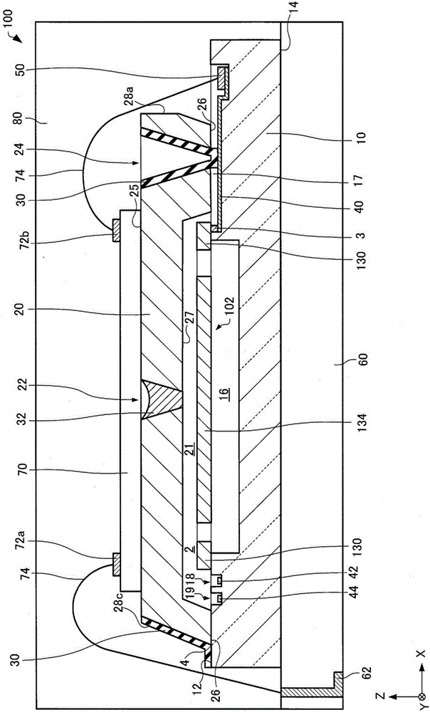
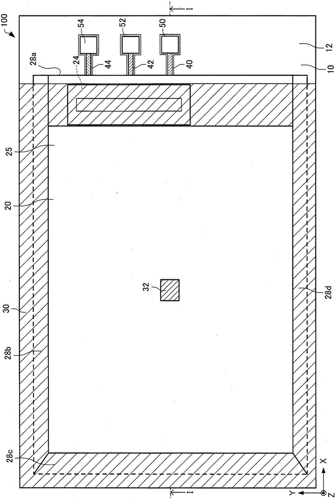
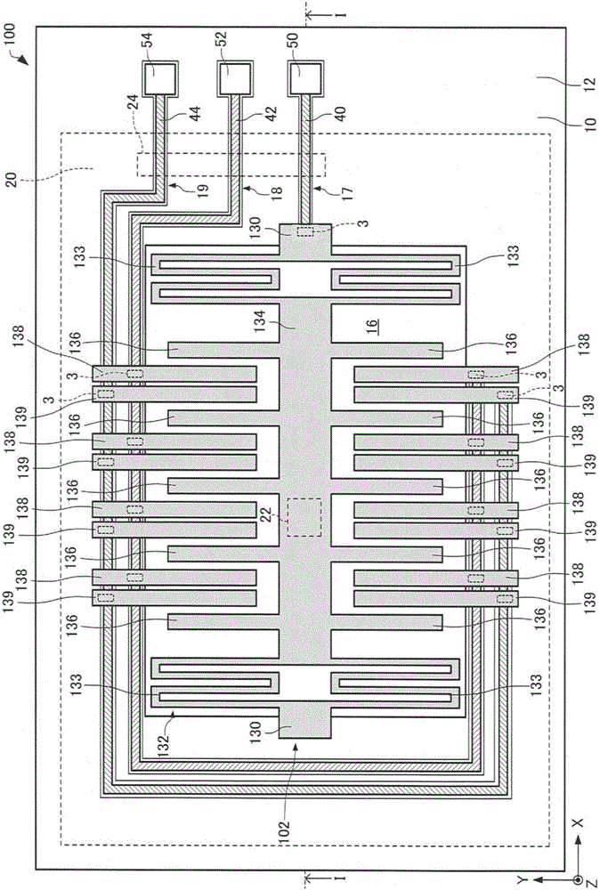
[0058] First, a physical quantity sensor according to the present embodiment will be described with reference to the drawings. figure 1 It is a cross-sectional view schematically showing the physical quantity sensor 100 according to this embodiment. figure 2 and image 3 It is a top view schematically showing the physical quantity sensor 100 according to this embodiment. in addition, figure 1 for figure 2 and image 3 Sectional view of the I-I line. In addition, in Figure 1 ~ Figure 3 In , the X axis, the Y axis, and the Z axis are shown as three mutual...


PUM


Abstract

The invention provides a physical quantity sensor, a manufacturing method thereof, electronic equipment, and a movable body. The physical quantity sensor can decrease the possibility that a cover might come off from a base. The physical quantity sensor (100) includes: a base (10); a cover (20); a function element (102) provided inside a cavity (2) formed by the base (10) and the cover (20); and a protection film (30) with which a principal surface (12) of the base (10), a bonding boundary portion (4) between the principal surface (12) of the base (10) and the cover (20), and the cover (20) are coated continuously, wherein the protection film (30) is an inorganic material film or an organic semiconductor film.

Description

technical field [0001] The present invention relates to a physical quantity sensor, a manufacturing method thereof, electronic equipment and a mobile body. Background technique [0002] In recent years, a physical quantity sensor that detects a physical quantity using silicon MEMS (Micro Electro Mechanical System: Micro Electro Mechanical System) technology has been developed. In particular, applications such as acceleration sensors that detect acceleration and gyro sensors that detect angular velocity are rapidly spreading, such as hand-shake correction functions for digital cameras (DSC), car navigation systems, and motion sensing functions for game consoles. [0003] In such a physical quantity sensor, a functional element is accommodated in a hermetically sealed cavity. [0004] For example, Patent Document 1 discloses a physical quantity sensor in which a functional element is arranged in a cavity formed by a base body and a cover body. In Patent Document 1, anodic bo...

Claims


Application Information

Patent Timeline
Patent Type & Authority Applications(China)
IPC IPC(8): G01D11/24G01P1/02B81B7/00
CPCB81B7/0058G01D11/245G01P1/023B81B2201/0235B81C1/00269G01P15/125G01P2015/0814
Inventor 成瀬敦纪
Owner SEIKO EPSON CORP
Learn More