Supercharge Your Innovation With Domain-Expert AI Agents!

Screw iron chip separation device for thread rolling machine

A separation device and thread rolling machine technology, applied in the field of machinery, can solve the problems that the separation device can only be applied to screws of a certain diameter, the gap between the conveying cylinder and the conveying worm cannot be adjusted, and the screws are mixed with iron filings and cooling oil, etc. To achieve the effect of simple structure, convenient operation and cost saving

Inactive Publication Date: 2016-09-21
ZHEJIANG KEJIA MACHINERY
View PDF5 Cites 1 Cited by
  • Summary
  • Abstract
  • Description
  • Claims
  • Application Information

AI Technical Summary

Problems solved by technology

[0004] Although the above scheme solves the problem that the screws processed by the existing thread rolling machine are mixed with iron filings and cooling oil to a certain extent, the scheme still exists: the gap between the conveying cylinder and the conveying worm cannot be adjusted, thus Problems such as making the separating device only suitable for screws of a certain diameter

Method used


Image

  • Screw iron chip separation device for thread rolling machine
  • Screw iron chip separation device for thread rolling machine
  • Screw iron chip separation device for thread rolling machine

Examples


Embodiment Construction

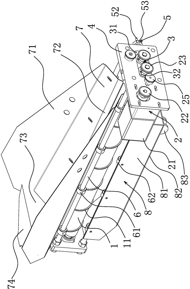
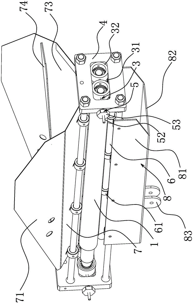
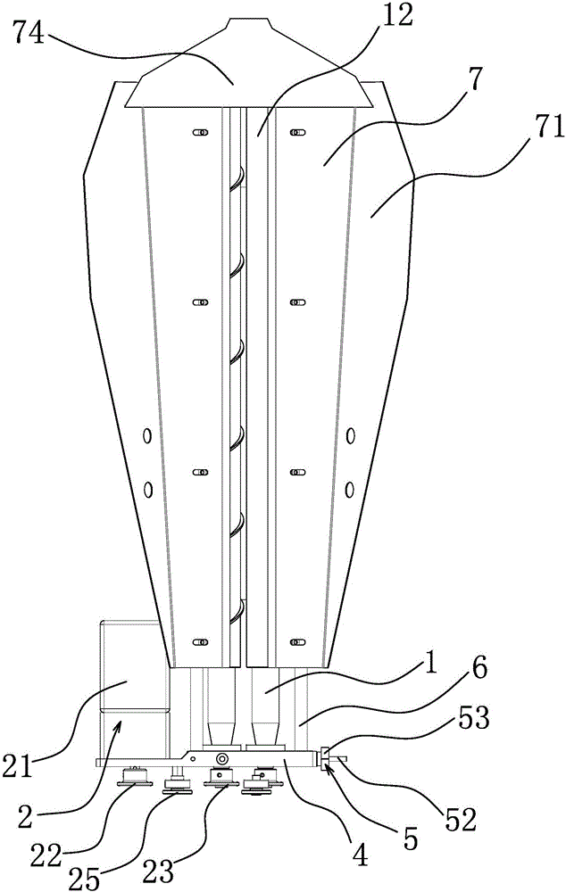
[0021] Such as Figure 1 to Figure 3 As shown, the screw chip separation device for thread rolling machine includes at least two conveying rods 1 corresponding to each other and arranged in parallel, at least one of the two conveying rods 1 has spirally distributed and self The spiral ribs 11 extending from one end of the conveying rod 1 to the other end form a gap 12 for the passage of iron filings between two adjacent conveying rods 1, and the conveying rods 1 are connected with a wire that enables the two adjacent conveying rods 1 to synchronize And the conveying driving mechanism 2 that rotates in the same direction in the circumferential direction is provided with a gap adjustment structure 3 between two adjacent conveying rods 1 that can make one of the two conveying rods 1 approach or move away from the remaining one so as to adjust the size of the gap 12 . Preferably, there are two conveying rods 1 , and the spiral rib 11 is arranged on one of the two conveying rods 1 ...


PUM


Abstract

The invention provides a screw iron chip separation device for a thread rolling machine, and solves such technical problems as incapability of adjusting a gap between a conveying cylinder and a conveying worm rod in the prior art. The screw iron chip separation device for the thread rolling machine comprises at least two conveying rods corresponding to each other and arranged in parallel; spiral convex ribs are spirally distributed at the outer periphery of at least one of the two conveying rods; a gap for passing through iron chips is formed between two adjacent conveying rods; the conveying rods are connected with conveying driving mechanisms capable of synchronizing two adjacent conveying rods and peripherally rotating two adjacent conveying rods; and a gap adjusting mechanism capable of approaching or separating the two conveying rods to adjust the size of the gap is arranged between two adjacent conveying rods. The screw iron chip separation device for the thread rolling machine has such advantages as simple structure, convenience for operation and capability of separating the screw iron chips of screws with different diameters through adjusting the size of the gap between the conveying rods by the gap adjusting mechanism.

Description

technical field [0001] The invention belongs to the technical field of machinery, and in particular relates to a screw scrap separating device for a thread rolling machine. Background technique [0002] Thread rolling machine is a professional production of thread equipment. The main working principle of the thread rolling machine is that the screw to be processed is placed in the thread rolling station, and under the driving force of the driving device, the screw plate squeezes the screw to form threads or silk screen patterns on the screw. However, after the screw is threaded by a traditional thread rolling machine, the surface of the screw coming out of the thread rolling machine contains a large amount of iron filings and cooling oil, which are directly collected into the storage box, making it difficult to clean the surface of the screw, and the iron filings are easy to Scratch the thread surface and affect the quality of the screw, and the cooling oil cannot be recycl...

Claims


Application Information

Patent Timeline
IPC IPC(8): B21H3/06
CPCB21H3/06
Inventor 马树荣
Owner ZHEJIANG KEJIA MACHINERY
Features
  • R&D
  • Intellectual Property
  • Life Sciences
  • Materials
  • Tech Scout
  • Unparalleled Data Quality
  • Higher Quality Content
  • 60% Fewer Hallucinations
Learn More