Cooling structure of sand coating machine for iron mold

A technology of cooling structure and sand-covering machine, which is applied to molding machines, parts of molding machines, casting molding equipment, etc., and can solve problems such as easy wear of sealing rings and unstable operation of supporting cylinders

Active Publication Date: 2016-09-21
CHONGQING HONGQI CYLINDER HEAD MFG
View PDF6 Cites 2 Cited by
  • Summary
  • Abstract
  • Description
  • Claims
  • Application Information

AI Technical Summary

Problems solved by technology

[0005] The present invention intends to provide a cooling structure for an iron sand coating machine to solve the p

Method used


Image

  • Cooling structure of sand coating machine for iron mold
  • Cooling structure of sand coating machine for iron mold

Examples


Embodiment Construction

[0017] The present invention will be described in further detail below by means of specific embodiments:

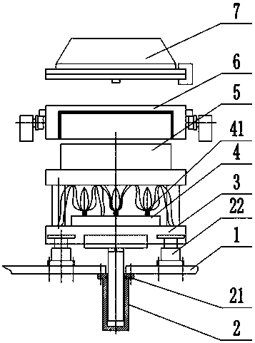
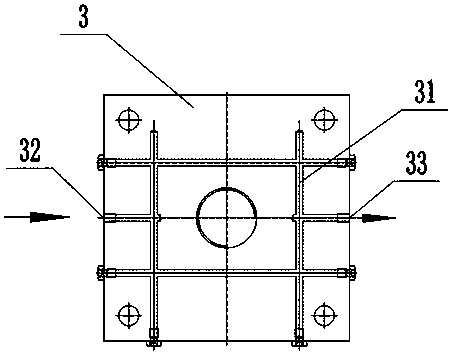
[0018] The reference signs in the drawings of the description include: mounting plate 1, supporting cylinder 2, sealing ring 21, auxiliary cylinder 22, bottom plate 3, cross flow channel 31, water inlet 32, drain 33, combustion plate 4, nozzle 41, mold 5 , sand box 6, sand shooting mechanism 7.

[0019] The embodiment is basically as attached figure 1 And attached figure 2 Shown:

[0020] The cooling structure of the iron type sand coating machine in this scheme is installed on the sand coating machine. The sand coating machine is installed with a sand shooting mechanism 7, a sand box 6 and a mold 5 in sequence from top to bottom. The sand shooting end of the sand shooting mechanism 7 and the The sand box 6 is connected, and the sand box 6 and the mold 5 are detachably connected. The bottom of the mold 5 is connected with a heating device. A sealing ring 21 is instal...


PUM


Abstract

The invention relates to a sand jetting part, and discloses a cooling structure of a sand coating machine for an iron mold. The cooling structure of the sand coating machine for the iron mold is arranged on the sand coating machine. The sand coating machine sequentially comprises a sand jetting mechanism, a sand box and a mold from top to bottom; the sand jetting end of the sand jetting mechanism is connected with the sand box; the sand box and the mold are detachably connected; a heating device is connected under the mold; a support cylinder is connected to the lower end of the heating device, and is fixedly connected onto an installation plate of the sand coating machine; a base plate is connected between the heating device and the support cylinder; a channel group for cooling water to pass through is arranged in the base plate; a water inlet and a water outlet communicating with the channel group are formed on the base plate. According to the technical scheme provided by the invention, the base plate for the water to pass through is utilized to prevent heat of the heating device from transmitting to the support cylinder, so that the temperature rise of the support cylinder is prevented, the influence of high temperature on the sealing effect of a sealing ring on the support cylinder is avoided, and the operation stability of the support cylinder is improved.

Description

technical field [0001] The invention relates to a sand shooting machine component. Background technique [0002] Iron mold sand-covered casting is a semi-precision casting method. This method uses a metal model and a cast iron cavity that is close to the shape of the casting as a sand box iron mold. The close-shaped iron mold is covered with a thin layer of coated sand to form Molds are used for pouring to make castings. Iron mold sand-covered casting has the characteristics of sand casting, that is, it has a rigid sand mold shell, which makes the overall strength of the sand mold high and does not deform, the casting is easy to demould, and the positioning is reliable and the precision is high, so it has a wide range of applications. The main technological process of sand-coated iron mold production includes several steps such as sand-covered molding, inspection and closing, locking the box and placing the sprue cup, pouring, unpacking the casting, sand cleaning, and moldi...

Claims


Application Information

Patent Timeline
IPC IPC(8): B22C15/24B22C19/00
CPCB22C15/24B22C19/00
Inventor 黄党怀
Owner CHONGQING HONGQI CYLINDER HEAD MFG
Why Eureka
Try Eureka