

Mucus drag reduction device for underwater vehicle
An underwater vehicle and drag reduction device technology, applied in transportation and packaging, ships, hydrodynamic characteristics/hydrostatic characteristics, etc. Guaranteed drag reduction effect
- Summary
- Abstract
- Description
- Claims
- Application Information
AI Technical Summary
Problems solved by technology
Method used
Image

Examples
Embodiment Construction
[0042] The present invention will be described in detail below with reference to the accompanying drawings and examples.
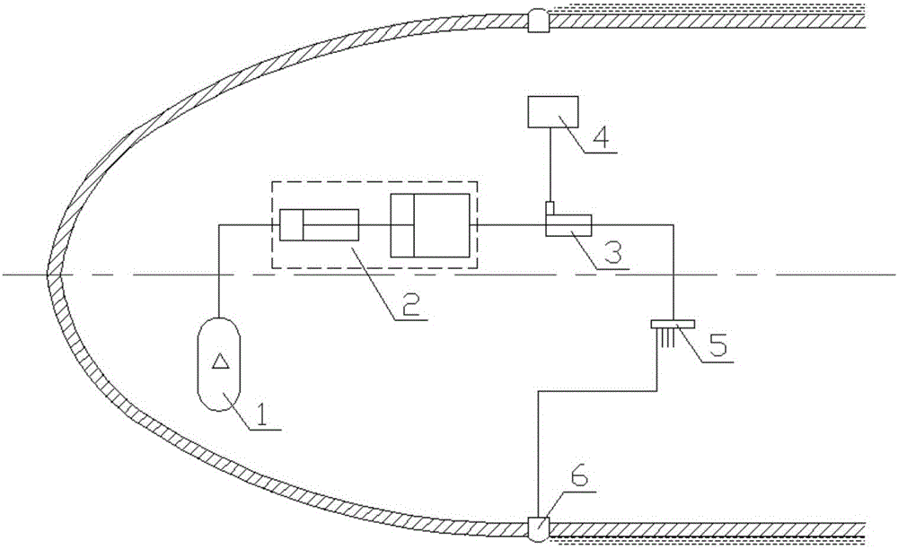
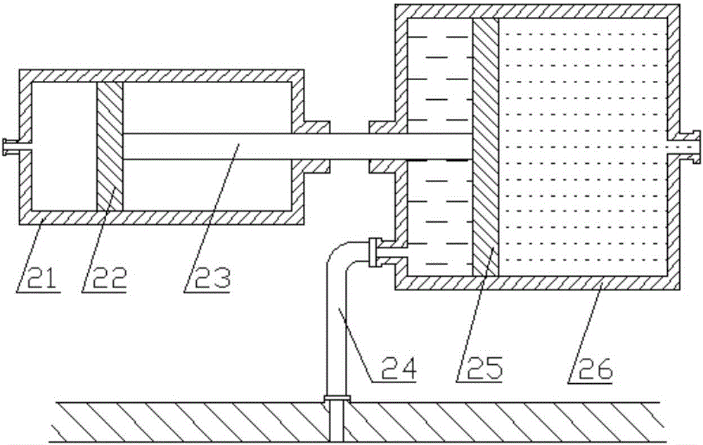
[0043] The invention provides an underwater vehicle mucus drag reducing device, see attached figure 1 , including: gas cylinder 1, double-body piston cylinder 2, flow control valve 3, controller 4, joint 5, mucus, gas pipe and liquid pipe;
[0044] Its peripheral equipment is an underwater vehicle;
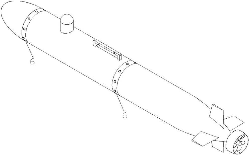
[0045] See attached image 3 , the parallel section of the underwater vehicle shell has one or two circles of mucus release holes 6 uniformly distributed along its circumferential direction; the axis of the mucus release holes 6 is inclined 30 degrees to the tail of the underwater vehicle; and the The number, size and shape of the mucus release holes 6 should consider the flow field distribution near the surface of the underwater vehicle, so that the mucus flowing out from the mucus release holes 6 can cover most of the surface of the underwater vehicle; if ...
PUM
 Abstract
Description
Claims
Application Information