An eccentric oil well pump

An oil well pump and eccentric technology, which is applied in the direction of pumps, pump components, variable capacity pump components, etc., can solve the problems of long oil inlet channel and large oil inlet resistance, and achieve the effect of reducing oil inlet resistance and improving strength

Active Publication Date: 2017-12-29
CHINA PETROLEUM & CHEM CORP +1
View PDF7 Cites 0 Cited by
  • Summary
  • Abstract
  • Description
  • Claims
  • Application Information

AI Technical Summary

Problems solved by technology

[0004] The purpose of the present invention is to provide an eccentric oil well pump, aiming at solving the problems of long oil inlet channel and large oil inlet resistance in the prior art

Method used


Image

  • An eccentric oil well pump

Examples


Embodiment Construction

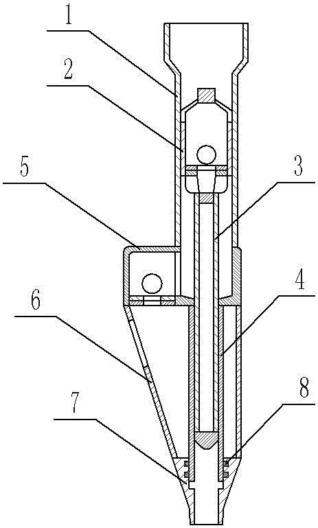
[0015] The embodiment of eccentric oil well pump among the present invention: as figure 1 As shown, the eccentric oil well pump is an eccentric bridge oil well pump used in thermal recovery of heavy oil wells in oil fields, including an upper pump barrel 1, an eccentric joint 5, a lower pump barrel 4, and a conversion joint 7 sequentially connected from top to bottom. , the upper pump barrel 1 and the lower pump barrel 4 are slidingly assembled with the upper plunger 2 and the lower plunger 3 along the up and down direction, the upper plunger 2 and the lower plunger 3 are connected to each other, and the upper and lower ends of the lower plunger 3 Both are closed; the eccentric joint 5 has a central part connected between the upper pump cylinder 1 and the lower pump cylinder 4 and an eccentric part offset to one side of the central part, and the eccentric part is equipped with a device for controlling the one-way flow of oil from bottom to top. The fixed valve is provided with...


PUM


Abstract

The invention discloses an eccentric oil pump. The lower end of a drainage channel of the oil pump is closed; and drainage ports communicating with the drainage channel are formed in the pipe wall of a drainage pipe, and are spaced above a lower port of a lower pump cylinder. An oil intake mode is offsetting oil intake, so that the pump has a shorter oil intake runner, and reduces the oil intake resistance. Meanwhile, when the gas injection is performed, steam is fed to a designed steam injecting position from the lower port of the lower pump cylinder by a pump lower tail pipe without direct backflow into the drainage channel for overflowing. When the thermal expansion generated in steam injection of the pump lower tail pipe under such special conditions as oil well sand discharge cannot be freely released, higher extruding force is generated on the pump. After the drainage pipe is added, the part for bearing the extruding force is changed from the lower pump cylinder with a smaller wall thickness to the drainage pipe with a larger wall thickness and a larger stress area, so that the strength of the lower pump cylinder is improved.

Description

technical field [0001] The invention relates to an eccentric oil pump. Background technique [0002] At present, the existing downhole eccentric oil well pumps for oil fields are usually mainly composed of upper and lower pump barrels and upper and lower plungers which are respectively in sealing and sliding cooperation with the inner walls of the upper and lower pump barrels. The upper and lower plungers are connected together, and the swimming valve is arranged at the bottom of the upper plunger. The upper and lower pump barrels are connected by an eccentric joint, and one side of the eccentric joint protrudes outward to form a fixed ball cover. A fixed ball is arranged inside the fixed ball cover. The bottom surface of the fixed ball cover has An oil inlet, the axis of the oil inlet is parallel to the axis of the lower plunger. The upper end of the large pump barrel is connected to the oil pipe to the wellhead, and the lower end of the lower pump barrel is connected to ...

Claims


Application Information

Patent Timeline
Patent Type & Authority Patents(China)
IPC IPC(8): F04B47/00F04B53/16F04B53/14F04B53/02
CPCF04B47/00F04B53/02F04B53/14F04B53/16
Inventor 胡英才刘若虚苗玉礼查旋李鹏杨玉山吴荷香
Owner CHINA PETROLEUM & CHEM CORP
Why Eureka
Try Eureka