System for suppressing forced vibration of centrifugal impeller and control method for system

A forced vibration, centrifugal impeller technology, applied in the field of compressors, can solve the problems of weakening the disc vibration, difficult to apply, unable to suppress the impeller blade vibration, etc., to achieve the effect of suppressing fatigue damage and increasing aerodynamic damping

Active Publication Date: 2016-09-21
HEFEI GENERAL MACHINERY RES INST
View PDF7 Cites 3 Cited by
  • Summary
  • Abstract
  • Description
  • Claims
  • Application Information

AI Technical Summary

Problems solved by technology

However, for a structure such as a centrifugal impeller, the damper can only weaken the vibration of the disc, but cannot suppress the vibration of the impeller blades excited by the airflow, and the dry friction damping structure is also difficult to apply to the blades of the centrifugal impeller
At the same time, the existing technologies all suppress the forced vibration from the aspect of improving structural damping, and it is necessary to install related equipment on the rotor components, which significantly increases the structural complexity

Method used


Image

  • System for suppressing forced vibration of centrifugal impeller and control method for system
  • System for suppressing forced vibration of centrifugal impeller and control method for system
  • System for suppressing forced vibration of centrifugal impeller and control method for system

Examples


Embodiment Construction

[0031] Below in conjunction with embodiment technical solution of the present invention is made more specific description:

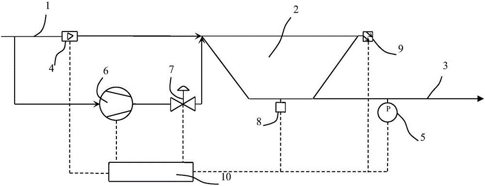
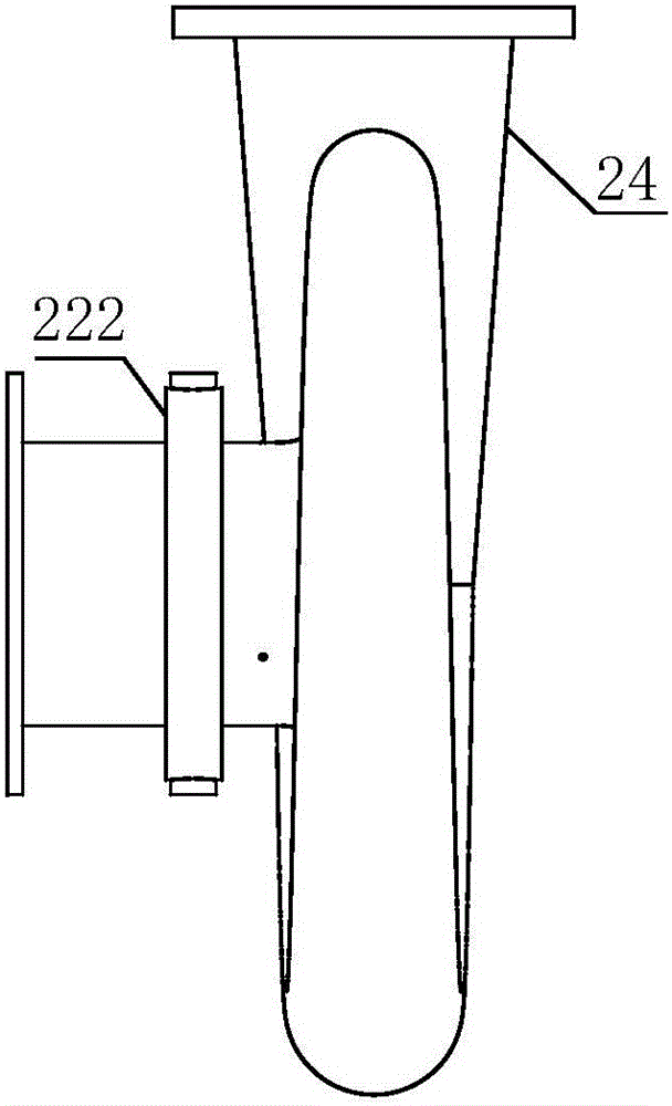
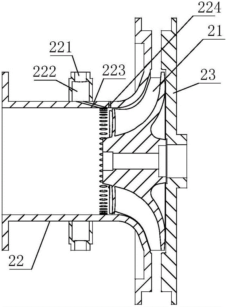
[0032] Such as figure 2 , 3 As shown, the centrifugal impeller forced vibration suppression system of the present invention includes a centrifugal compressor 2, the front of the impeller 21 of the centrifugal compressor 2 is a casing cover plate 22, and the casing cover plate 22 forms an air suction channel, and the suction An annular air collection chamber 222 is provided on the outer peripheral surface of the air passage, and a jet air inlet 221 communicating with the air intake passage 1 is provided on the annular air collection chamber 222. The gas collection chamber 222 communicates with the spray hole 223 that sprays the spray air to the front of the impeller 21 to suppress the vibration of the impeller. The axial direction of the spray hole 223 is arranged toward the impeller 21 . The impeller 21 is a semi-open impeller. In the present inventi...


PUM


Abstract

The invention mainly relates to a system for suppressing forced vibration of a centrifugal impeller. The system comprises a centrifugal compressor. A housing cover plate is disposed in front of an impeller of the centrifugal compressor and forms an air suction channel. An annular air accumulation chamber is disposed on an external peripheral surface of the air suction channel, and provided with a jet air stream inlet communicating with an air inlet channel. A plurality of jet holes communicating with the air accumulation chamber and used for jetting a jet air stream to a position in front of the impeller to inhibit the vibration of the impeller are uniformly formed in the air suction channel in a peripheral direction with each jet hole axially facing the impeller. The system for suppressing forced vibration of a centrifugal impeller is provided with the annular air accumulation chamber on the housing cover plate; a jet air stream enters the annular air accumulation chamber via the jet air stream inlet and then is uniformly jetted via the jet holes to a region in front of the impeller; the jet air stream forms a local flow field for blocking the vibration of the impeller under appropriate pressure and at an appropriate angle of attack, thereby achieving an aerodynamic damping effect and allowing effective suppression of the fatigue damage of the centrifugal impeller caused by air stream excitation under complicated operating conditions.

Description

technical field [0001] The invention belongs to the technical field of compressors, and in particular relates to a forced vibration suppression system of a centrifugal impeller and a control method thereof. Background technique [0002] Modern centrifugal compressors are developing in the direction of high load, high efficiency and high reliability. The centrifugal impeller, as its core component, often experiences flow conditions such as elbow intake distortion, upstream guide vane wake, and stall clusters in actual operation. , resulting in unsteady aerodynamic forces acting on the blades, thereby inducing forced vibration of the impeller. Under extreme working conditions, the centrifugal impeller is excited by the air flow to produce a large alternating stress, which is superimposed on the static stress caused by the centrifugal force, which may lead to fatigue damage of the impeller blades. It is of great significance to reduce fatigue and improve structural reliability...

Claims


Application Information

Patent Timeline
Patent Type & Authority Applications(China)
IPC IPC(8): F04D29/68F04D27/02
CPCF04D27/02F04D29/684
Inventor 肖军赵远扬杨启超
Owner HEFEI GENERAL MACHINERY RES INST
Why Eureka
Try Eureka