
Space docking error compensation mechanism

An error compensation and space docking technology, which is applied to projectiles, self-propelled projectiles, offensive equipment, etc., can solve the problems of difficult adjustment of initial posture, poor matching of spring parameters, and difficulty in selecting spring parameters, and achieves light weight and structure. Simple, low additional force effect

Inactive Publication Date: 2016-09-21
赵纯
View PDF7 Cites 7 Cited by
  • Summary
  • Abstract
  • Description
  • Claims
  • Application Information

AI Technical Summary

Problems solved by technology

[0003] The Chinese invention patent CN104596363A discloses a space docking error compensation mechanism for a launch vehicle connector system, which includes 6 spring guide rod devices, 12 ball hinges, a connector panel and a suspension platform. The above compensation mechanism can compensate for the above-mentioned deviation. However, It is a general form of 6-SPS mechanism. The adjustment of each ball hinge directly affects 6 degrees of freedom. The initial pose is not easy to adjust. In addition, the spring parameters are not easy to match. If the connector panel has mass eccentricity, it is difficult to choose a suitable one. Furthermore, using multiple ball hinges, due to the gaps in the ball hinges, it is easy to produce posture deviations, and the rotation angle of the ball hinges is limited, which limits the compensation range

Method used


Image

  • Space docking error compensation mechanism
  • Space docking error compensation mechanism
  • Space docking error compensation mechanism

Examples


Embodiment Construction

[0020] Below in conjunction with accompanying drawing and embodiment the present invention will be further described:

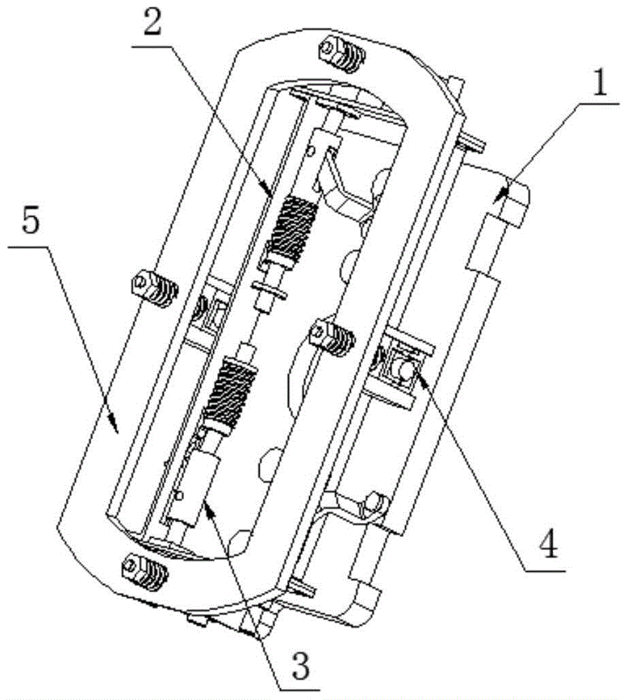
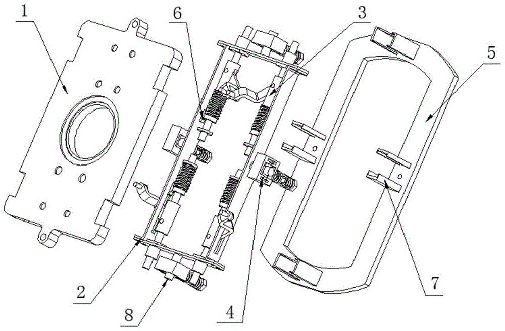
[0021] Such as Figure 1 to Figure 4 As shown, a space docking error compensation mechanism includes: an integrated connector panel 1, a frame structure 2, four link devices 3, four multi-degree-of-freedom joint devices 4 and a reference panel 5. In order to reduce the volume, four The link devices 3 are symmetrically distributed inside the frame structure 2, the integrated connector panel 1 and the frame structure 2 are connected by four link devices 3, and the frame structure 2 and the reference panel 5 are connected by four The multi-degree-of-freedom joint device 4 is connected.

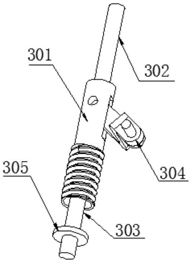
[0022] Specifically, the connecting rod device 3 includes a threaded pipe 301, a first guide rod 302, a second guide rod 303, a spring and a folded connecting plate 304, one end of the first guide rod 302 and the second guide rod 303 One end has an external thread adapted to t...


PUM


Abstract

The invention relates to the technical field of carrier rocket ground refueling devices, and particularly discloses a space docking error compensation mechanism. The space docking error compensation mechanism includes an integrated connector panel, a frame structure, four connection rod devices, four multi-degree of freedom joint devices and a reference panel; the four connection rod devices are symmetrically distributed in the inner part of the frame structure; the integrated connector panel is connected to the frame structure through the four connection rod devices; and the frame structure is connected to the reference panel through the four multi-degree of freedom joint devices. According to the technical scheme, the execution mechanism is flexibly connected the integrated connector panel, damage to the connector structures and a rocket structure due to position and angle errors existing between the reference panel and a movable door panel can be avoided during docking, moving, and falling of the connector system.

Description

technical field [0001] The invention relates to the technical field of launch vehicle ground filling equipment, in particular to a space docking error compensation mechanism. Background technique [0002] In terms of the connector of the launch vehicle ground filling system, in order to realize the automatic docking and detachment of the connector and the launch vehicle, and to avoid the difficulty of centering and follow-up caused by the swing of the rocket body with the wind during the docking and filling process, the first thing to solve The designed automatic docking and disconnecting connector system has position and angle errors between the reference panel and the valve panel in the process of docking, following and falling off, so as to avoid the damage of the connector structure and the rocket body structure caused by the above deviation. [0003] The Chinese invention patent CN104596363A discloses a space docking error compensation mechanism for a launch vehicle con...

Claims


Application Information

Patent Timeline
Patent Type & Authority Applications(China)
IPC IPC(8): F42B15/36
CPCF42B15/36
Inventor 赵纯李保平孙同生
Owner 赵纯
Learn More