Mobile robot real-time layered path planning method based on grid map
A mobile robot, path planning technology, applied in two-dimensional position/channel control and other directions, can solve problems such as not a global path, no local minimum or oscillation problem, etc.
- Summary
- Abstract
- Description
- Claims
- Application Information
AI Technical Summary
Problems solved by technology
Method used
Image
Examples
specific Embodiment approach 1
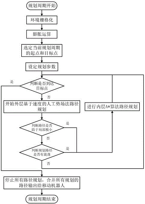
[0030] Specific implementation mode one: Clarify the goal of the robot path planning and initialize it: the computer equipped with the mobile robot establishes and updates the grid map containing the external environment information in real time through the acquisition equipment, determines the starting point and target point of the plan, and applies the speed-based artificial potential field method and A The star algorithm is used for hierarchical path planning to ensure that the robot runs to the target point in real time, safely and stably.
specific Embodiment approach 2
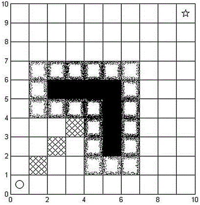
[0031] Specific implementation mode two: This implementation is a further description of a real-time layered path planning method for mobile robots based on grid maps. When the size of the grid map is equal to When , the computational complexity of the A* path planning method can reach . If the grid granularity in this environment model is changed to half of the original, the grid scale will become , and the calculation amount will increase to . Therefore, although A* can guarantee to find an optimal path, it cannot guarantee the real-time motion of the mobile robot.
[0032] Although the velocity-based artificial potential field method is more suitable for real-time path planning due to its simplicity, local minimum phenomena and possible shocks will cause the robot to run unstable. Due to the nature of the potential field, if the parameters are not selected properly, the robot may ignore the physical contact and only regard it as the interaction of the field, and t...
specific Embodiment approach 3
[0034] Specific implementation mode three:This implementation is a further description of a real-time layered path planning method for mobile robots based on grid maps. The Euclidean distance of is inversely proportional, when the gravitational potential energy is zero, the mobile robot reaches the target point. The gravitational potential energy function is expressed as:
[0035] ;
[0036] in is the gravitational gain coefficient; Represents a vector whose size is the current position and target position Euclidean distance between , the direction of the vector is and The position on the line connecting the two positions from the robot position to the target point.
[0037] Then the gravitational force generated by the gravitational potential field is:
[0038] ;
[0039] gravitational direction and in the same direction.
[0040] The Euclidean distance between the repulsive potential energy and gravitational potential energy received by the mobile ...
PUM
 Abstract
Description
Claims
Application Information
 - R&D
- Intellectual Property
- Life Sciences
- Materials
- Tech Scout
- Unparalleled Data Quality
- Higher Quality Content
- 60% Fewer Hallucinations
Browse by: Latest US Patents, China's latest patents, Technical Efficacy Thesaurus, Application Domain, Technology Topic, Popular Technical Reports.
© 2025 PatSnap. All rights reserved.Legal|Privacy policy|Modern Slavery Act Transparency Statement|Sitemap|About US| Contact US: help@patsnap.com


