Eureka AIR delivers breakthrough ideas for toughest innovation challenges, trusted by R&D personnel around the world.

Wireless charging equipment and method for multi-rotor aircraft

A technology of multi-rotor aircraft and wireless charging equipment, which is applied to electrical components, circuit devices, etc., can solve problems such as troublesome operation and short continuous working time of multi-rotor aircraft, and achieve the effect of solving charging difficulties and improving convenience

Active Publication Date: 2016-09-21
ZONECHARGE (SHENZHEN) WIRELESS POWER TECH CO LTD
View PDF3 Cites 9 Cited by
  • Summary
  • Abstract
  • Description
  • Claims
  • Application Information

AI Technical Summary

Problems solved by technology

[0003] The multi-rotor aircraft is equipped with a radio remote control system, which has the characteristics of easy operation, free switching of various flight modes, and flexible direction control. Therefore, with the development of multi-rotor aircraft technology, the application field of multi-rotor aircraft is continuously expanding, and it is used to record Aerial video, agricultural monitoring, plant protection, security patrol and other applications, but limited by battery technology and charging technology, the continuous working time of multi-rotor aircraft is extremely short, especially in automatic cruise work such as agricultural monitoring, plant protection, security patrol, etc. The field application has been greatly restricted
[0004] At present, the battery charging of the multi-rotor aircraft is generally performed by removing the battery and inserting the battery into the battery charger, which is more troublesome.

Method used


Image

  • Wireless charging equipment and method for multi-rotor aircraft
  • Wireless charging equipment and method for multi-rotor aircraft
  • Wireless charging equipment and method for multi-rotor aircraft

Examples


Embodiment 1

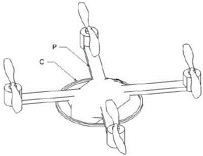
[0033] In this embodiment, a quadrotor aircraft is used as an example for illustration. The structure of the quadrotor aircraft is the prior art in this field, and will not be described in detail in this embodiment. Only the quadrotor aircraft is used to explain the wireless charging device of the present invention. .

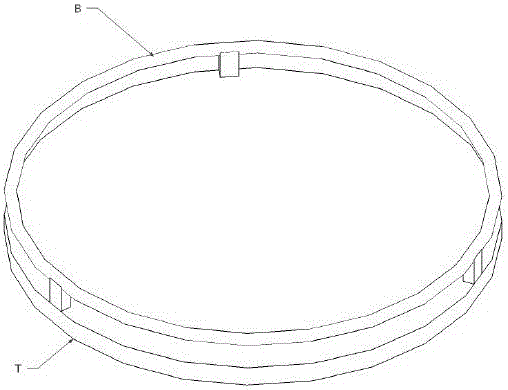
[0034] in the attached figure 1 , attached Figure 4 Among them, a wireless power transmitting device A is installed on the apron T of this embodiment, wherein the wireless power transmitting device A includes a wireless power transmitting circuit E, a wireless power transmitting coil B electrically connected with the wireless power transmitting circuit E; The circuit E is installed inside the apron T, and the specific layout is shown in the drawings; the wireless energy transmitting coil B is installed parallel to the surface of the apron T. The wireless power transmitting coil B is arranged around the outer contour of the apron T, and the wireless power tra...

Embodiment 2

[0054] In this example, the overall structure and charging process of the charging device are similar to Embodiment 1, only further changes are made in the installation of the wireless energy transmitting coil and the wireless energy receiving coil. In this embodiment, the quadrotor aircraft is still taken as an example .

[0055] In this embodiment, the wireless energy transmitting coil can also be laid directly on the upper surface of the apron T, and attention should also be paid to the arrangement of the wireless energy transmitting coil B around the outer contour of the apron T during laying.

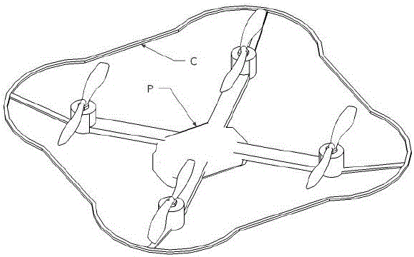
[0056] The wireless energy receiving coil is installed on the periphery of the rotor, and the four ends of the four rotors are surrounded into a ring shape, which not only realizes the electromagnetic wave transmission with the wireless energy transmitting coil, but also forms an anti-collision barrier to protect the quadrotor aircraft.


PUM


Abstract

The invention belongs to the field of wireless power supply, and particularly relates to wireless charging equipment and method for a multi-rotor aircraft. The wireless charging equipment for the multi-rotor aircraft comprises a wireless power transmitting device located on a parking apron, and a wireless power receiving device located on the multi-rotor aircraft, wherein the wireless power transmitting device comprises a wireless power transmitting circuit and a wireless power transmitting coil; the wireless power transmitting coil is electrically connected with the wireless power transmitting circuit; the wireless power receiving device comprises a wireless power receiving coil and a wireless power conversion circuit; the wireless power conversion circuit is electrically connected with the wireless power receiving coil; and the wireless power transmitting coil is wirelessly connected with the wireless power receiving coil through an electromagnetic wave. Power transmission is carried out between the transmitting coil and the receiving coil through electromagnetic energy, and charging is carried out by a constant-current constant-voltage charging mode in the charging process. A battery of the multi-rotor aircraft is charged through a wireless power transmission mode; and the problem in charging is solved for continuous operation of the multi-rotor aircraft.

Description

technical field [0001] The invention belongs to the field of wireless power transmission, and in particular relates to a wireless charging device and method for a multi-rotor aircraft. Background technique [0002] A multi-rotor aircraft is an aircraft that has multiple rotors with a positive angle of attack at the same time to generate lift and rotate in different directions to overcome the anti-torsion force. There are three-rotor, four-rotor, six-rotor, eight-rotor and other multi-rotor aircraft. For example, a four-rotor aircraft uses four rotors as the direct power source for flight, and the rotors are symmetrically distributed in the front, rear, left and right directions of the body. The four rotors are at the same height plane, and the structures and radii of the four rotors are the same. Rotor 3 rotates counterclockwise, and rotor 2 and rotor 4 rotate clockwise. The four motors are symmetrically installed on the bracket end of the aircraft, and the flight control c...

Claims


Application Information

Patent Timeline
Patent Type & Authority Applications(China)
IPC IPC(8): H02J50/00
Inventor 蔡伟杰徐宝华许向东朱斯忠
Owner ZONECHARGE (SHENZHEN) WIRELESS POWER TECH CO LTD
Why Eureka
Eureka Blog
Learn More