Electromagnetic oven
A technology of induction cooker and circuit board, applied in the field of induction cooker, can solve problems such as affecting the service life of the induction cooker, and achieve the effect of reducing the difficulty of processing and assembly
- Summary
- Abstract
- Description
- Claims
- Application Information
AI Technical Summary
Problems solved by technology
Method used
Image


Examples
Embodiment 1
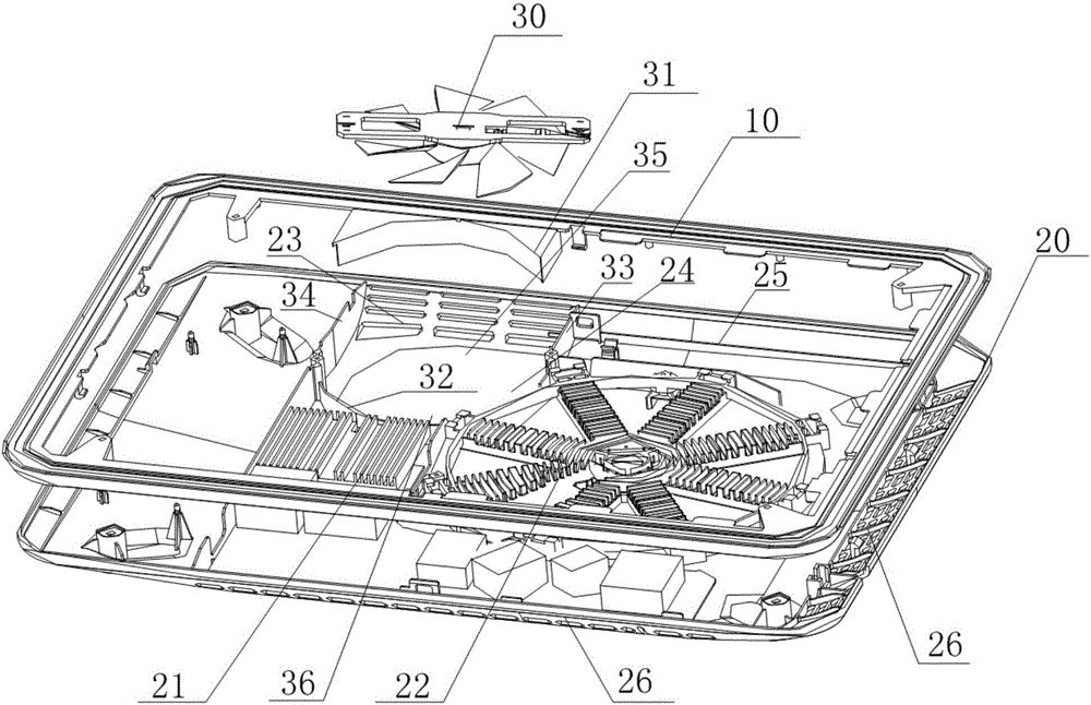
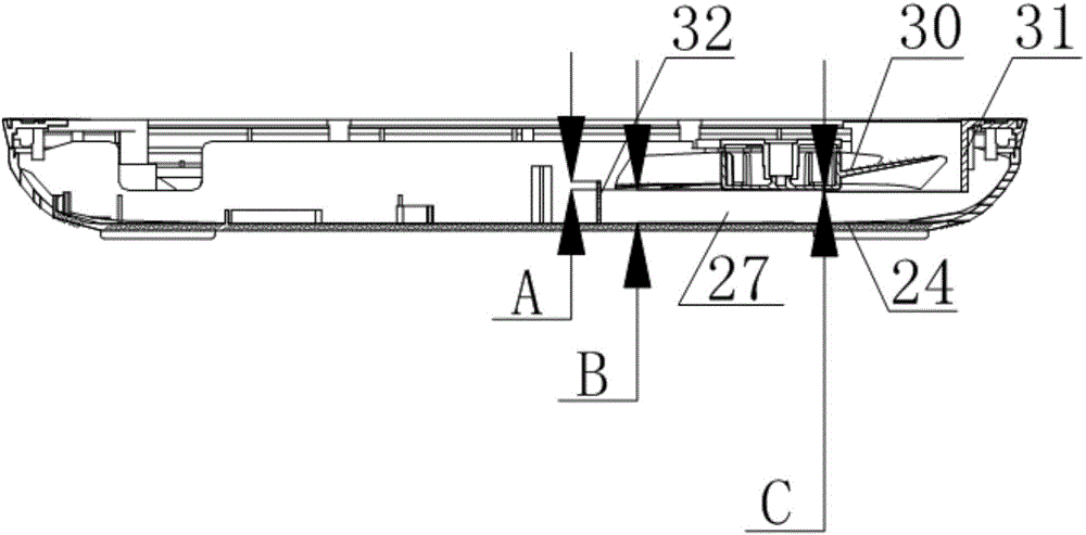
[0038] figure 1 It is a structural schematic diagram of an electromagnetic oven according to Embodiment 1 of the present invention, figure 2 It is a side view of the electromagnetic oven of the present invention. like figure 1 and figure 2 As shown, the present embodiment provides an induction cooker, including: an upper cover 10, a cover plate (not shown) arranged on the top surface of the upper cover 10, a bottom case 20, a circuit board 21 arranged in the bottom case 20, and a coil disk 22. The fan 30 and the air guide cover arranged on the periphery of the fan 30, the side wall 25 of the bottom shell 20 is provided with a side air inlet 23, and the side of the air guide cover near the side air inlet 23 is provided with a fan air inlet 35, the guide A fan air outlet 36 is arranged on the side of the windshield close to the inside of the induction cooker, and at least part of the windshield is arranged on the upper cover 10 .
[0039] In this embodiment, pots and the l...
Embodiment 2
[0052] image 3 It is a structural representation of an electromagnetic oven according to Embodiment 2 of the present invention Figure 1 , Figure 4 It is a structural representation of an electromagnetic oven according to Embodiment 2 of the present invention Figure II . like image 3 and Figure 4 As shown, the wind deflector 31 is disposed on the upper cover 10 , and the wind deflector 32 is disposed on the bottom wall 24 of the bottom case 20 .
[0053] Furthermore, there is a gap at the junction of the wind deflector 31 and the wind deflector 32 forming the wind guide, which easily makes the wind leak. Therefore, in order to prevent air leakage at the junction, in this embodiment, one end of the wind deflector 32 has a blocking portion, and the blocking portion overlaps with one end of the wind deflector 31, or the wind deflector 31 has a blocking portion. One end has a blocking portion, and the blocking portion is overlapped with one end of the wind deflector 32 ...
Embodiment 3
[0059] Figure 5 It is a schematic structural representation of an electromagnetic oven according to Embodiment 3 of the present invention Figure 1 ; Image 6 for Figure 5 The enlarged schematic diagram of the blocking slot of the induction cooker shown; Figure 7 It is a schematic structural representation of an electromagnetic oven according to Embodiment 3 of the present invention Figure II ; Figure 8 for Figure 7 An enlarged schematic diagram of the blocking slot of the induction cooker shown.
[0060] Figure 5 to Figure 7 It is shown that one end of the wind deflector 32 has a blocking groove. Specifically, one end of the wind-outlet windshield 32 has a barrier 342 , and the other end of the wind-outlet windshield 32 has a first wind-collecting plate 33 .
[0061] Please refer to Figure 5 and Image 6 ,exist Figure 5 and Image 6 In the illustrated embodiment, the fan 30 rotates clockwise, and the wind generated by the fan 30 is a clockwise wind, so as...
PUM
 Abstract
Description
Claims
Application Information
 - R&D
- Intellectual Property
- Life Sciences
- Materials
- Tech Scout
- Unparalleled Data Quality
- Higher Quality Content
- 60% Fewer Hallucinations
Browse by: Latest US Patents, China's latest patents, Technical Efficacy Thesaurus, Application Domain, Technology Topic, Popular Technical Reports.
© 2025 PatSnap. All rights reserved.Legal|Privacy policy|Modern Slavery Act Transparency Statement|Sitemap|About US| Contact US: help@patsnap.com