Swing type steel pipe feeding device

A feeding device and swing type technology, applied in the field of swing type steel pipe feeding device, can solve the problems of increasing the workload of equipment management personnel, lack of long-term stability of the gear rack, and many transmission links of the cylinder force, so as to reduce the Maintenance and inspection work intensity, guarantee the opening and closing effect, and reduce the effect of the transfer link

Active Publication Date: 2017-07-21
CHANGSHU MEILI MACHINERY MFG
View PDF3 Cites 0 Cited by
  • Summary
  • Abstract
  • Description
  • Claims
  • Application Information

AI Technical Summary

Problems solved by technology

This patent scheme can objectively reflect the technical effect summarized in paragraph 0014 of its description, but there are the following shortcomings: First, because the feed mechanism adopts a structure in which gears and racks cooperate, the reduction motor installed on the base Drive the gear, the gear drives the rack, and the rack drives the feed trolley, so that the feed trolley, together with the traversing mechanism, turning mechanism, clamping mechanism and discharge mechanism set with the feed trolley as the carrier, move (paragraph 0028 of the manual) ), so the structure of the feed mechanism is complicated, especially in the actual use process, the gears and racks of the structure system of the feed mechanism need to be regularly or irregularly maintained (such as lubricating oil), which increases the equipment The workload of the management and maintenance personnel. In addition, the lasting stability of the rack and pinion movement is relatively lacking, and it is easily damaged, causing trouble for replacement; The mechanism and the discharge mechanism are mounted on the feed trolley in the form of a guide rail pair with the feed trolley, and since the feed trolley forms a rolling pair through the rollers and the base, in order to ensure that the steel pipe can be aligned with a group of heading machines The center of the header block needs to be guaranteed by a traversing mechanism. However, the applicant believes that if the structure is reasonable, the traversing trolley can be abandoned, otherwise the complexity of the overall structure will be further increased; third, due to the clamping The cylinder of the mechanism is connected with the tongs through the active rod, connecting rod and sliding rod (equipped with a guide sleeve) in turn, that is, the cylinder is directly connected to the tongs through the performance of the cylinder, so the force transmission link of the cylinder If there are too many, the force loss is large, which is not conducive to the reliable clamping of the steel pipe by the clamp. Of course, increasing the power of the cylinder can avoid this unfavorable factor, but increasing the power of the cylinder is not conducive to energy saving; The upper part of the feeding trolley is the feeding trolley, the upper part of the feeding trolley is the traversing trolley, and the upper part of the traversing trolley is the discharging mechanism. In addition, the distance between the turning mechanism and the top of the clamping mechanism and the feeding trolley is relatively large, so not only The volume of the whole device is significantly increased, and the turning mechanism and the clamping mechanism lose stability because the center of gravity is far away from the feeding trolley

Method used


Image

  • Swing type steel pipe feeding device
  • Swing type steel pipe feeding device
  • Swing type steel pipe feeding device

Examples


Embodiment Construction

[0021] In order to facilitate a clearer understanding of the technical essence and beneficial effects of the present invention, the applicant will describe in detail the following in the form of examples, but the description of the examples is not a limitation to the solution of the present invention. Equivalent transformations that are only formal but not substantive should be regarded as the scope of the technical solution of the present invention.

[0022] In the following descriptions, all concepts related to directionality or orientation of up, down, left, right, front and back are based on figure 1 The shown position status is a reference, so it cannot be understood as a special limitation on the technical solution provided by the present invention.

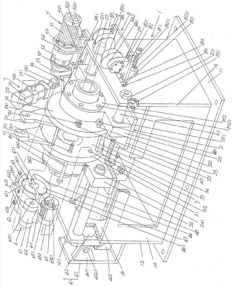
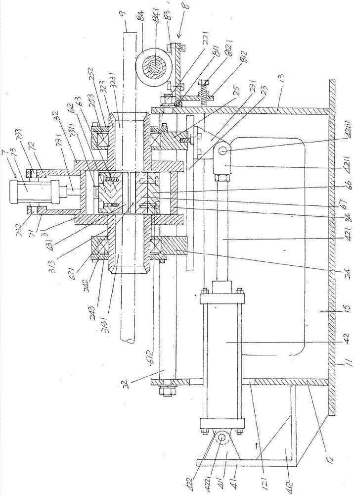
[0023] See figure 1 and figure 2 , shows a frame 1, the frame 1 is set on the floor of the place of use corresponding to the position of the head block of the steel pipe heading machine in the use state, the steel pipe h...


PUM


Abstract

The invention discloses an oscillating type steel pipe feeding device and belongs to the field of seamless steel pipe processing machines. The oscillating type steel pipe feeding device comprises a rack, a mobile trolley arranged on the upper portion of the rack, an oscillating mechanism supported on the mobile trolley, a feeding mechanism connected with the mobile trolley, an oscillating disc driving mechanism connected with the oscillating mechanism, a clamp mechanism arranged on the oscillating mechanism, a clamp opening and closing driving mechanism arranged on the oscillating mechanism and connected with the oscillating mechanism, and a steel pipe supporting and protecting guide mechanism arranged at the right end of the rack. The oscillating type steel pipe feeding device is characterized in that the feeding mechanism comprises a feeding action cylinder fixing base and a feeding action cylinder; the feeding action cylinder fixing base is fixed to the left end of the rack; the feeding action cylinder is connected with the feeding action cylinder fixing base; a feeding action cylinder column is connected with the mobile trolley; the clamp opening and closing driving mechanism and the clamp mechanism are connected; and the oscillating disc driving mechanism is arranged on the rear side of the right end of the mobile trolley. By means of the oscillating type steel pipe feeding device, the structure is simplified, and the labor intensity is relieved; the acting force transmission link is omitted, and the opening and closing effect of the clamp mechanism is ensured; and the motion stability is good, and occupied space is small.

Description

technical field [0001] The invention belongs to the technical field of seamless steel pipe processing machinery, and specifically relates to a swing type steel pipe feeding device, which is matched with a steel pipe header, and sends one end of a steel pipe to be headed into the steel pipe header, and exits the steel pipe after the header is completed Header. Background technique [0002] The steel pipe heading machine mentioned above is also called "pipe shrinking machine". It is a special equipment before seamless steel pipe drawing. Its function is to complete the seamless steel pipe blank (seamless steel pipe blank) Also known as "capillary" or "barren pipe"), one end forms a narrowed steel pipe head with a diameter significantly smaller than the diameter of the seamless steel pipe body, so that the caliper of the cold drawing machine can clamp the steel pipe head during the cold drawing process , that is, the drawing is performed under the condition that the caliper cl...

Claims


Application Information

Patent Timeline
Patent Type & Authority Patents(China)
IPC IPC(8): B21C5/00
CPCB21C5/003
Inventor 王伟陈东武薛志军吕斌
Owner CHANGSHU MEILI MACHINERY MFG
Why Eureka
Try Eureka