Hydraulic T-beam formwork construction device and technology

A technology of construction equipment and beam formwork, which is applied in the direction of mold panels, molds, manufacturing tools, etc., can solve the problems of large formwork amortization, low formwork utilization rate, and long idle time of side forms, so as to improve utilization rate and installation efficiency , The effect of lower hoisting operation risk

Inactive Publication Date: 2016-09-28
中交二公局第四工程有限公司
View PDF7 Cites 8 Cited by
  • Summary
  • Abstract
  • Description
  • Claims
  • Application Information

AI Technical Summary

Problems solved by technology

[0004] In order to overcome the problems of long idle time of side forms, low formwork utilization rate and large formwork amortization in the existing device, the present invention provides a hydraulic T-beam formwork construction device, which adopts hydraulic movable integral formwork, formwork assembly, The adjustment is convenient and fast, the position is accurate, and the seams are closely bonded; the use of hydraulic movable side forms not only improves the efficiency of formwork installation, lowers the risk of hoisting operations, reduces the labor intensity of workers, and improves the utilization rate of side forms

Method used


Image

  • Hydraulic T-beam formwork construction device and technology
  • Hydraulic T-beam formwork construction device and technology

Examples


Embodiment 1

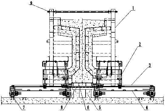
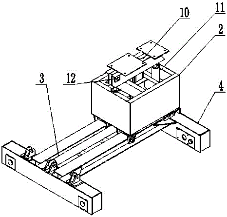
[0030] In order to overcome the problems of long idle time of the side molds in the existing device, low template utilization rate and large template amortization, the present invention provides such figure 1 , figure 2 The hydraulic T-beam formwork construction device shown in the figure adopts a hydraulically movable integral formwork, which is convenient and fast for formwork assembly and adjustment, accurate in position, and close-fitting seams; the use of hydraulically movable sideforms not only improves the efficiency of formwork installation , Lower hoisting operation risk, reduce labor intensity of workers, and improve the utilization rate of side forms. Compared with the traditional hydraulic T-beam formwork, it increases the functions of vertical adjustment and vertical beam movement, and the utilization rate of the side formwork system can be increased by 2-3 times.

[0031] A hydraulic T-beam formwork construction device, comprising a side form 1, a beam moving t...

Embodiment 2

[0039] Based on the first embodiment, in this embodiment, the lower part of the connecting shoulder beam 10 is connected to the vertical oil cylinder 11 through the connecting pin 12 .

[0040] The lower end of the vertical oil cylinder 11 is fixed on the beam moving trolley 2 by bolts.

[0041] The lower end of the side mold 1 is fixedly connected with the bottom mold through a bottom tie rod 8 crossing the middle of the bottom mold 6 .

[0042] The bottom mold 6 is set on the concrete foundation surface 5, and a 150*150*20 steel plate is pre-embedded when pouring the concrete pedestal foundation surface, and the bottom mold 6 is welded to the concrete foundation surface 5 pre-embedded steel with 18 I-beams. One.

[0043] The lower part of the connecting shoulder beam 10 is connected with the vertical oil cylinder 11 through a pin connection, and the vertical oil cylinder 11 is located between the left and right side molds 1 .

[0044] The middle part of the side form 1 is ...

Embodiment 3

[0056] On the basis of the above-mentioned embodiments, in this embodiment, a hydraulic T-beam formwork construction process is provided, and the specific steps are:

[0057] Step 1 Check the device, all components are in normal function, and the longitudinal beam stops moving longitudinally when moving to the moving trolley 4 and reaching the end line of the bottom mold 6;

[0058] Step 2: The trolley 2, which moves the crossbeam in the direction of the beam, realizes the lateral movement on the translation equalizing beam through the horizontal translation oil cylinder, and closes the hydraulic system when the distance close to the bottom mold 6 is 1-2 cm;

[0059] Step 3 After step 2 is completed, stick to the bottom mold 6 through the bottom tie rod 8;

[0060] Step 4 After the above steps are completed, the column of the side form 1 is supported on the rigid foundation of the beam-making pedestal, the bottom of the side form 1 is fixedly connected with the bottom form 6 t...


PUM


Abstract

The invention provides a hydraulic T-beam formwork construction device. The device comprises lateral formworks, cross beam direction moving trolleys, horizontal hydraulic oil cylinders, longitudinal beam direction moving trolleys, a concrete pedestal foundation surface and a bottom formwork, wherein the bottom formwork is arranged on the concrete pedestal foundation surface; lower ends of the lateral formworks are connected with the bottom formwork; the upper end of the left lateral formwork and the upper end of the right lateral formwork are connected by the aid of a top pull rod; middles of the lateral formworks are connected with connecting pole beams; lower sides of the connecting pole beams are connected with vertical oil cylinders; lower ends of the vertical oil cylinders are fixed on the cross beam direction moving trolleys; one end of each cross beam direction moving trolley is connected with the horizontal hydraulic oil cylinder in a hinged manner, and the other end of the horizontal hydraulic oil cylinder is fixedly connected onto the longitudinal beam direction moving trolley. With the adoption of the movable hydraulic integrated formworks, the formworks are convenient and quick to assemble and adjust and take place accurately, and joints are closely attached; with the adoption of the movable hydraulic lateral formworks, the mounting efficiency of the formworks is improved, the lifting operation risk is reduced, the labor intensity of workers is reduced, and the utilization rate of the lateral formworks is increased.

Description

technical field [0001] The invention relates to a hydraulic T-beam formwork construction device and technology. Background technique [0002] At present, in the prefabricated construction of T-beams, the side forms are generally designed in sections, and the splicing length is 4 meters or 8 meters. The disassembly and installation of the formwork requires the assistance of gantry cranes or other hoisting equipment, and one set of side forms is used for every 2-3 pedestals. Due to the long length of a single section of the formwork, the formwork is greatly deformed during the process of hoisting and disassembling the formwork, the risk of the hoisting operation is high, and the labor intensity of the workers is high. It is highly dependent on hoisting equipment and the work efficiency is not high. There are many seams in the length direction of the formwork, making adjustment difficult, and the external dimensions and appearance quality of the beam are not easy to control. ...

Claims


Application Information

Patent Timeline
Patent Type & Authority Applications(China)
IPC IPC(8): B28B7/00B28B23/02
CPCB28B7/0029B28B7/0055B28B23/02
Inventor 吴洪群王豪李海亮阮明和刘尚芳李捷杨巍张建伟刘洪厂
Owner 中交二公局第四工程有限公司
Why Eureka
Try Eureka