Rapid die

A mold and rapid technology, applied in the direction of forming tools, manufacturing tools, metal processing equipment, etc., can solve problems such as difficult to truly reflect consumer problems, so as to speed up the time to seize the market, save mold costs, and reduce mold opening costs Effect

Active Publication Date: 2016-09-28
福建省加成信息技术有限公司
View PDF5 Cites 5 Cited by
  • Summary
  • Abstract
  • Description
  • Claims
  • Application Information

AI Technical Summary

Problems solved by technology

However, this kind of laboratory test is difficult to truly reflect the problems consumers encounter when using the product
Therefore, laboratory testing can only reduce but cannot avoid mold scrapping caused by mold repairing process, or structural errors and market elimination of products.

Method used


Image

  • Rapid die
  • Rapid die
  • Rapid die

Examples


Embodiment 1

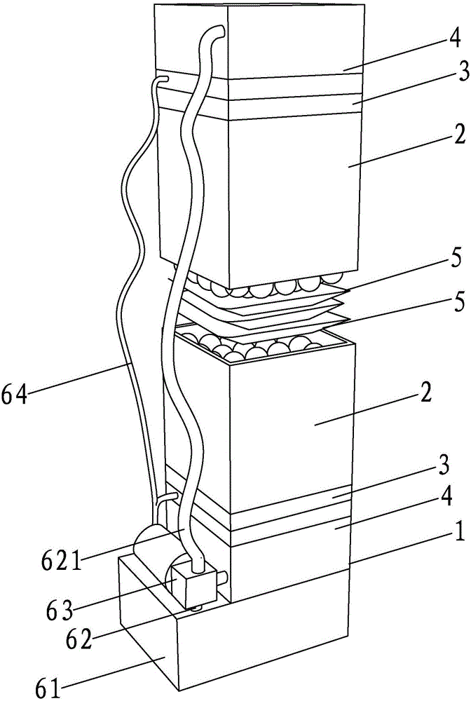
[0046] A rapid tooling such as figure 1 As shown, it includes a closed mold shell 1, two sets of mold units, a mold forming control device and an oil supply device, wherein one set of mold units forms the upper mold of the mold, and the other set of mold units forms the lower mold of the corresponding mold upper mold.

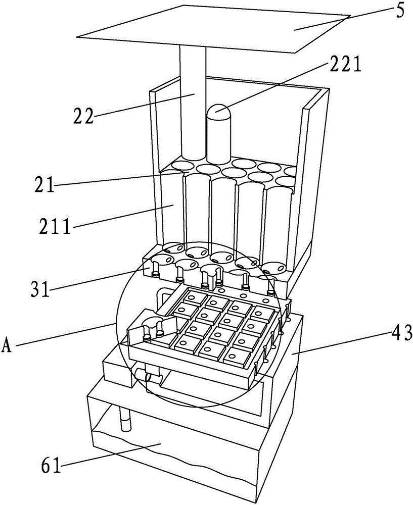
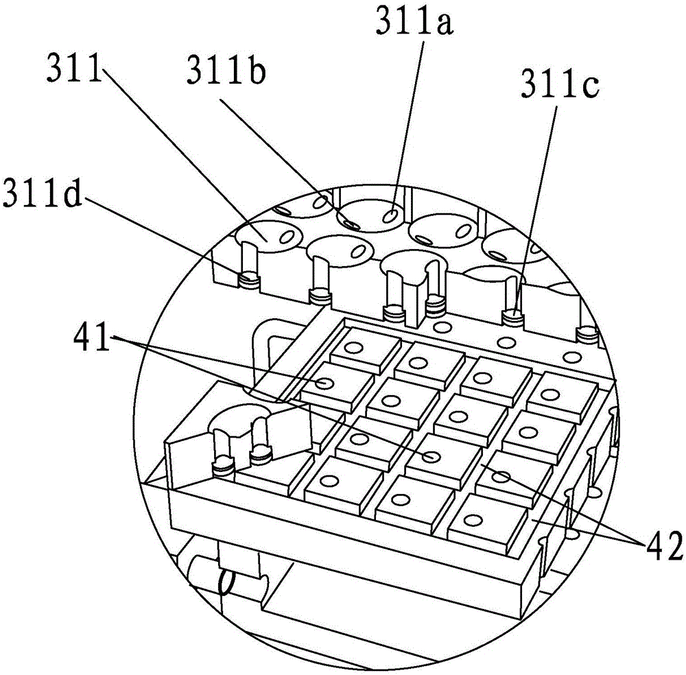
[0047] Such as figure 1 As shown, each set of mold units includes a mold assembly module 2, a movement control module 3, an inlet and outlet oil channel module 4, and a molding module. The oil passage module 4 is arranged vertically in the mold shell 1 from bottom to top in turn, and the molding module, mold combination module 2, movement control module 3 and oil passage module 4 in the mold unit corresponding to the lower mold of the mold are sequentially arranged from top to bottom Vertically arranged in the mold shell 1, the molding module in the mold unit corresponding to the upper mold of the mold and the molding module in the mold unit corresponding to t...

Embodiment 2

[0058] The difference between this embodiment and Embodiment 1 is that the rapid mold includes six sets of mold units, of which two sets of mold units are arranged symmetrically up and down to form corresponding mold upper molds and mold lower molds, and the other four sets of mold units are respectively arranged on the mold Form mold side mold around mold and mold lower mold, and mold shell comprises the mold upper shell that is arranged on the outside of mold upper mold, the mold lower shell that covers is arranged on the mold lower mold that is connected with each other, and four covers are arranged on respectively. Mold side shells outside the individual mold side molds. The lower end of the upper shell of the mold is provided with a fitting edge inclined outwards, the upper end of the lower shell of the mold is also inclined outwards with an upper fitting edge, and the upper end of each mold side shell is inclined outwards and is provided with a joint with the upper shell ...


PUM


Abstract

The invention discloses a rapid die. The rapid die comprises a closed die outer shell, one or more die units, a die formation control device and an oil supplying device. Each die unit comprises a die combination module, a motion control module, an oil inlet/outlet line module and a formation module. Each die combination module comprises a hydraulic oil cylinder and multiple hydraulic ejection rods which are arranged and combined according to a certain array and densely distributed. Each motion control module comprises an oil mass control oil cylinder which communicates with the corresponding hydraulic oil cylinder and is used for controlling the corresponding hydraulic ejection rods to ascend and descend. Each oil inlet/outlet line module comprises oil inlet pipelines used for oil inlet, oil outlet pipelines used for oil drainage and a high pressure oil tank used for supplying oil. The oil supplying device comprises an oil supplying pool, an oil supplying pipeline and a high pressure oil pump mounted on the oil supplying pipeline. By means of the rapid die, a die with a corresponding cavity can be combined directly and rapidly; by means of the combined die, injection molding parts or stamping parts can be produced rapidly; it is convenient to open the die and release the parts from the die; and the rapid die is applicable to mass production.

Description

technical field [0001] The invention relates to the technical field of mold forming, in particular to a rapid mold. Background technique [0002] In the process of modern industrial production and manufacturing, molds play an important role. Mold, that is, a tool that makes a blank into a product with a specific shape and size under the action of external force, is widely used in blanking, forming stamping, die forging, cold heading, extrusion, powder metallurgy parts pressing, pressure casting, and engineering plastics In the forming process of compression molding or injection molding of plastic, rubber, ceramics and other products, it is the mother of manufacturing industry. [0003] 3D printing technology belongs to a kind of rapid prototyping technology. It is a technology based on model files to construct objects by layer-by-layer stacking and cumulative molding. At present, 3D printing technology is widely used in various fields, especially In the mold industry of th...

Claims


Application Information

Patent Timeline
Patent Type & Authority Applications(China)
IPC IPC(8): B29C45/26B29C45/80B21D37/02
CPCB21D37/02B29C45/26B29C45/80
Inventor 陈振斌陈铭君
Owner 福建省加成信息技术有限公司
Why Eureka
Try Eureka