Novel lifting device for building

A lifting device and construction technology, applied in the direction of lifting device, lifting frame, lifting equipment safety device, etc., can solve the problems of safety protection, hidden danger, reduce the performance and application scope of building devices, etc., and achieve flexible height lifting adjustment. Effect

Inactive Publication Date: 2016-09-28
CHENGDU XUNDE SCI & TECH
View PDF10 Cites 14 Cited by
  • Summary
  • Abstract
  • Description
  • Claims
  • Application Information

AI Technical Summary

Problems solved by technology

[0002] In the process of building construction, it is often necessary to use corresponding support plates or support frames so that construction personnel can carry out building construction at higher places. In the current conventional building construction, the scaffolding is directly fixed on the outer wall. As a result, it is impossible to perform flexible height lifting to meet the different needs of construction personnel; at the same time, during the construction process, construction personnel often need to move on the construction platform or supporting device, and the existing construction platforms often do not provide protection for the construction personnel. Sufficient safety protection, which easily leads to corresponding safety hazards, which greatly reduces the performance and scope of application of building devices

Method used


Image

  • Novel lifting device for building

Examples


Embodiment Construction

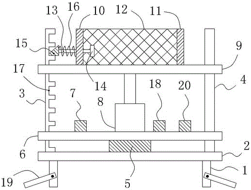
[0013] Such as figure 1 As shown, a new type of building lifting device includes a bracket 1 and a base plate 2 located on the bracket 1. A left pole 3 extending vertically upwards is fixed on the left end of the base plate 2. The right strut 4 extending vertically upwards is provided with a load cell 5 in the middle of the top of the base plate 2, and a support plate 6 parallel to the base plate 2 is also provided above the base plate 2, and the left and right ends of the support plate 6 are respectively provided with There are a left support plate through hole and a right support plate through hole (not shown in the figure), and the support plate 6 is slidably connected with the left support rod 3 and the right support rod 4 through the left support plate through hole and the right support plate through hole respectively, Also be respectively provided with microcontroller and LCD display 7 on support plate 6, and the output end of load cell 5 is connected to the input end of...


PUM


Abstract

The invention relates to a novel lifting device for a building. The novel lifting device comprises a support and a bottom plate. A left supporting rod is arranged at the left end of the bottom plate, and a right supporting rod is arranged at the right end of the bottom plate. A weighing sensor is arranged in the middle of the top of the bottom plate. A supporting plate is arranged above the bottom plate and is in sliding connection with the left supporting rod and the right supporting rod through a left supporting plate through hole and a right supporting plate through hole. The supporting plate is provided with a microcontroller, an LCD and a hydraulic cylinder. The top end of a piston rod of the hydraulic cylinder is connected with a top plate. The top plate is in sliding connection with the left supporting rod and the right supporting rod through a left top plate through hole and a right top plate through hole. The top plate is further provided with a left baffle and a right baffle. A front protection net and a rear protection net are arranged between the left baffle and the right baffle. A transverse inserting rod is inserted in a left baffle through hole of the left baffle in an embedded manner, a handle is arranged at the right end of the transverse inserting rod, and a limiting block is arranged at the left end of the transverse inserting rod. The part, located on the left of the left baffle, of the transverse inserting rod is sleeved with a spiral spring. A plurality of limiting clamping grooves are formed in the right side of the left supporting rod from top to bottom. By means of the above structure, the flexible height lifting adjustment can be conducted, and a constructor can be fully protected.

Description

technical field [0001] The invention relates to a novel building lifting device. Background technique [0002] In the process of building construction, it is often necessary to use corresponding support plates or support frames so that construction personnel can carry out building construction at higher places. In the current conventional building construction, the scaffolding is directly fixed on the outer wall. As a result, it is impossible to perform flexible height lifting to meet the different needs of construction personnel; at the same time, during the construction process, construction personnel often need to move on the construction platform or supporting device, and the existing construction platforms often do not provide protection for the construction personnel. Sufficient safety protection will easily lead to corresponding safety hazards, which greatly reduce the performance and scope of application of building devices. Contents of the invention [0003] In o...

Claims


Application Information

Patent Timeline
Patent Type & Authority Applications(China)
IPC IPC(8): B66F7/08B66F7/06B66F7/28B66F17/00
CPCB66F7/0625B66F7/08B66F7/28B66F17/00
Inventor 龚素华
Owner CHENGDU XUNDE SCI & TECH
Why Eureka
Try Eureka