

Induction quenching device and heat treatment system
A technology of induction hardening equipment and inductors, used in heat treatment furnaces, heat treatment equipment, quenching devices, etc., can solve the problem that the workpiece is prone to soft belts, and achieve the effect of avoiding soft belt problems and uniform heating
Image

Examples
Embodiment 1
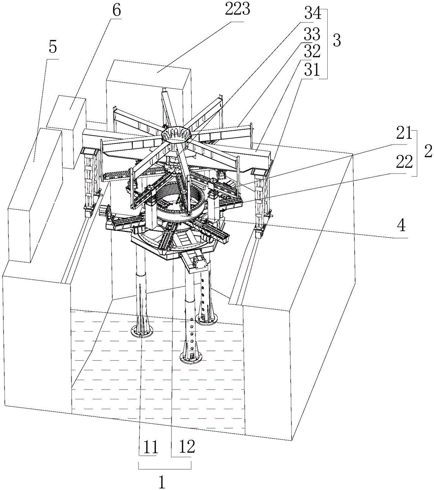
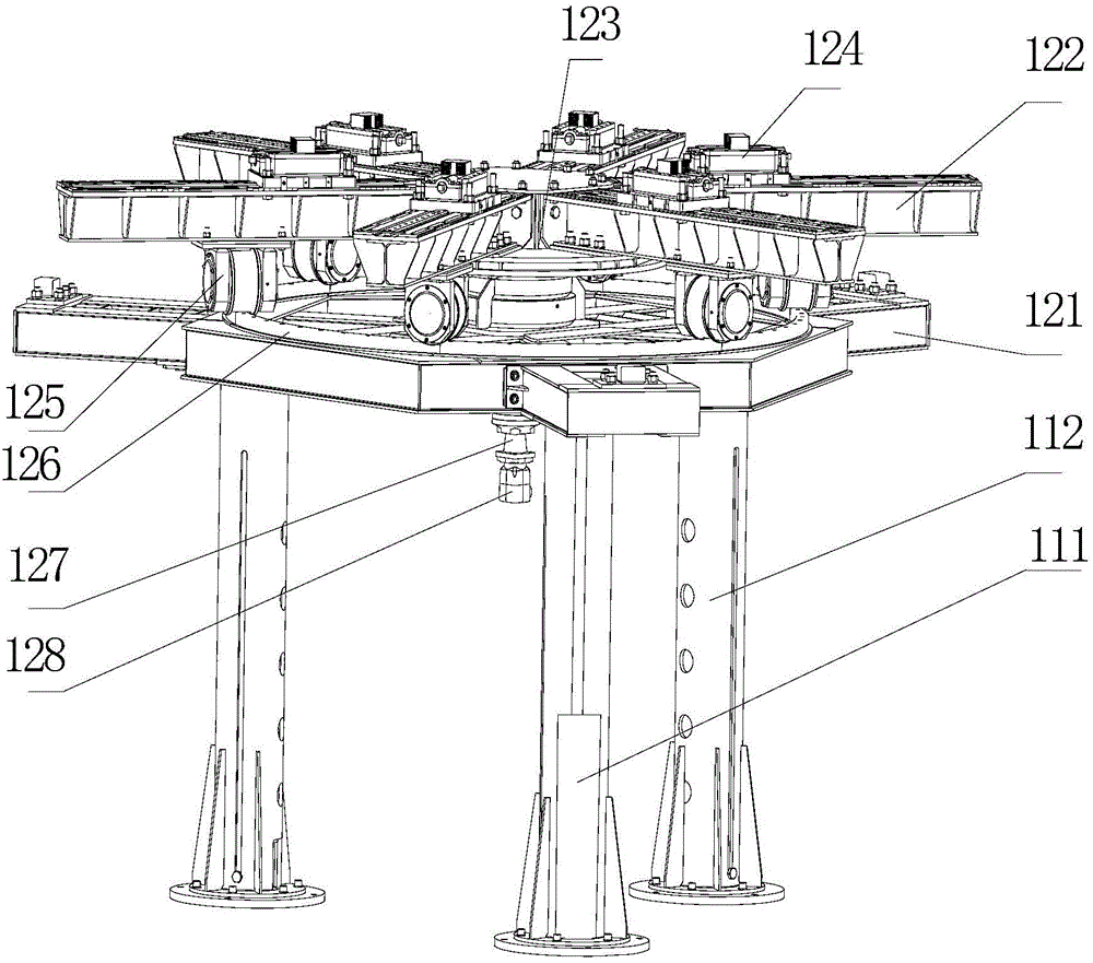
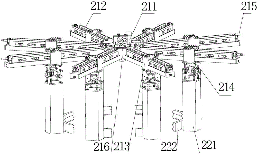
[0058] to combine Figure 1 to Figure 4 As shown, the induction hardening equipment provided in the first embodiment includes a workpiece platform 1 and a quenching induction device 2 . Wherein, the workpiece platform 1 is used to install the workpiece 4 to be processed, and the quenching induction device 2 includes an inductor bracket 21 and a plurality of quenching heating inductors 22 arranged on the inductor bracket 21, and a plurality of quenching heating inductors 22 are used to enclose It is used in the working area where the workpiece 4 is heated as a whole. The shape and size of this working area can be flexibly set depending on the condition of the workpiece 4. For example, when the workpiece 4 is in the shape of a ring, the shape of the working area also corresponds to a ring-shaped area, so that the workpiece 4 is heated more evenly. It can be seen that the induction hardening equipment adopts the overall heating and quenching method. Compared with the existing sc...
Embodiment 2
[0082] Embodiment 2 provides a heat treatment system, which includes a cooling pool and the induction hardening equipment in Embodiment 1; wherein, the cooling pool is used to cool the workpiece 4 heated by the induction hardening equipment, and the cooling pool can be a preset pool body , add quenching liquid in the pool body. The induction hardening equipment is correspondingly arranged above the cooling pool, and the heated workpiece 4 can be put into the cooling pool as a whole for cooling.
[0083] The heat treatment system can realize the quenching treatment of the slewing bearing. Combine below Figure 1 to Figure 4Be specific. The induction hardening equipment includes a workpiece platform 1 and a quenching induction device 2 . Wherein, the workpiece platform 1 is arranged in the cooling pool, and the workpiece platform 1 is used to install the slewing support to be processed, and can drive the slewing support to perform lifting and rotating movements. The quenchin...
PUM
 Abstract
Description
Claims
Application Information
- IPC
- C21D1/42; C21D1/62; C21D9/40
- CPC
- C21D1/42; C21D1/62; C21D9/40; Y02P10/25
- Inventors
- 肖礼志; 赵玉坤