
Tire burst detection method and cavity type tire burst sensor

A tire blowout sensor and tire blowout technology, applied in the field of tire blowout detection, can solve the problems of reducing the size and weight of tire blowout and tire pressure monitoring modules, so as to facilitate large-scale mass production and meet long-term low power consumption and stable work , the effect of reducing volume and weight

Active Publication Date: 2016-09-28
GUILIN SICHAO AUTO TECH
View PDF6 Cites 0 Cited by
  • Summary
  • Abstract
  • Description
  • Claims
  • Application Information

AI Technical Summary

Problems solved by technology

[0004] The purpose of the present invention is to solve the technical problem by using the principle of compressible air and the characteristics of the measuring hole to balance the air pressure inside and outside the sealed cavity within a limited time, to provide a tire burst sensor structure integrated into the tire burst and tire pressure monitoring module structure, No fatal failure caused by leakage, no mechanical contact and switch contact fatigue, no need to consider the tire blowout detection technology solution for the air pollution switch contact problem inside the tire; because the structure of the blowout sensor is integrated into the blowout and tire pressure monitoring module shell Among them, the volume and weight of the tire blowout and tire pressure monitoring module are greatly reduced

Method used


Image

  • Tire burst detection method and cavity type tire burst sensor
  • Tire burst detection method and cavity type tire burst sensor
  • Tire burst detection method and cavity type tire burst sensor

Examples


Embodiment 1

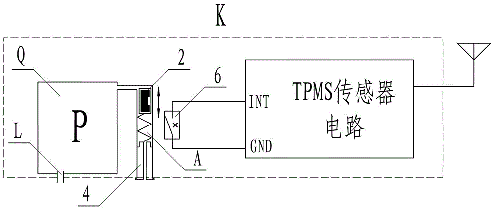
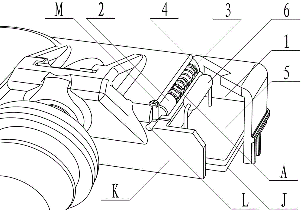
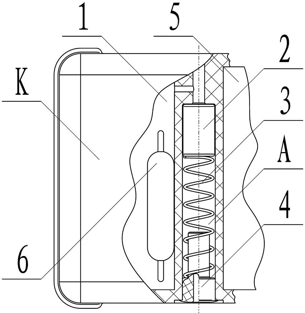
[0017] Combine below figure 1 , figure 2 , image 3 The tire burst sensor of Embodiment 1 of the present invention will be described in detail.

[0018] The tire burst sensor consists of a semi-open chamber (1), a permanent magnet piston (2), a spring (3), a plug (4), and a PCB board (5) arranged in the tire burst and tire pressure monitoring module housing (K). It is composed of a reed switch (6); a tube-shaped air passage (A) connected to the semi-open cavity (1) and parallel to the wheel axis is provided in the tire burst and tire pressure monitoring module housing (K); in the semi-open The cavity (1) is provided with a measuring hole (L) passing through the semi-open cavity (1); the measuring hole (L) is adjusted to achieve the dynamic characteristics required by different tire pressures through the screw (M) for adjusting the flow rate; The permanent magnet piston (2) is a permanent magnet whose surface is wrapped or coated with a solid lubricating material (such as: ...

Embodiment 2

[0021] Combine below figure 1 , figure 2 , image 3 The tire burst sensor of Embodiment 2 of the present invention will be described in detail.

[0022] As a change, the measuring hole (L) of embodiment 2 is arranged in the tubular air passage (A), and the permanent magnetic piston (2) is not coated with silicone grease, and is installed in a dry manner. By accurately adjusting the permanent magnetic piston (2 ) cooperates with the gap of the tubular air channel (A) to realize the adjustment function of the flow rate of the metering hole (L), and can also reduce the adjustment links; the magnetic sensitive switch can also choose an active Hall switch;

[0023] Although embodiment 2 has made some adjustments on the structure of the measuring hole. Relative to embodiment 1, there is no essential change; the installation of the tire burst sensor in embodiment 2, and the tire burst monitoring method of the tire burst sensor are all the same as in embodiment 1.


PUM


Abstract

The invention discloses a tire burst detection method and a cavity type tire burst sensor, and provides a technical scheme for solving the problems of leakage-free catastrophic failure, long-time pressure contact fatigue of sensing element and switches and atmosphere pollution in a tire. According to the invention, the tire burst sensor is small in volume, sensing elements do not contact and press the switches in most conditions, only when gas pressure inside the sensing elements is higher than external gas pressure and tire burst signals need to be output, can the switches be pressed, and the tire burst detection method accords with actual needs of tire burst detection.

Description

technical field [0001] The invention relates to a tire blowout monitoring technology for pneumatic tires for vehicles, in particular to a tire blowout detection method, a tire blowout sensor structure and a method for using the blowout sensor. Background technique [0002] Existing tire blowout sensors all adopt independent structures, and a compressible elastic sealed cavity filled with a certain gas is used as a sensitive element; the sensitive element is compressed under air pressure conditions, and when the tire burst air pressure disappears, the sensitive element restores its shape and touches The switch outputs a puncture signal; this method can effectively detect any form of puncture, but the leakage of the sealed cavity will cause the fatal failure of the puncture sensor, and high-density materials must be used for the manufacture of the sealed cavity. [0003] Secondly, the adjustment of action parameters is complicated, which is not conducive to large-scale mass pr...

Claims


Application Information

Patent Timeline
Patent Type & Authority Applications(China)
IPC IPC(8): G01L17/00
CPCG01L17/00
Inventor 彭世益彭彦钧
Owner GUILIN SICHAO AUTO TECH
Learn More