
Method for determining shrinkage rate of glass

A technology of shrinkage and glass, which is applied in the direction of measuring devices, instruments, thermal expansion coefficient of materials, etc., can solve problems such as difficult to measure glass shrinkage, glass has bubbles, irregular shape, etc., and achieves high reproducibility, high precision, The effect of accurate measurement results

Inactive Publication Date: 2016-09-28
WUHU DONGXU OPTOELECTRONICS EQUIP TECH +2
View PDF6 Cites 15 Cited by
  • Summary
  • Abstract
  • Description
  • Claims
  • Application Information

AI Technical Summary

Problems solved by technology

The size of the finished glass is regular and large, the thickness is uniform, and the heat shrinkage test is easy to implement and has high reproducibility; It is impossible to manufacture flat glass with relatively large size, high surface quality, and uniform thickness as on the production line to provide experimental reference data, that is, it is difficult to measure the shrinkage rate of glass with irregular shape and small size by the aforementioned heat shrinkage measurement method

Method used


Image

  • Method for determining shrinkage rate of glass
  • Method for determining shrinkage rate of glass
  • Method for determining shrinkage rate of glass

Examples


preparation example Construction

[0029] In the method of the present invention, preferably, in step (1), the preparation method of the glass filament to be tested comprises: drawing the glass into a glass filament, and after cutting, firing the two ends of the glass filament into a spherical shape.

[0030] The glass melted from different materials is drawn into glass filaments with uniform diameter and the same diameter with a wire drawing machine. Preferably, the diameter of the drawn glass filaments is 0.3-1mm, more preferably 0.5-0.8mm. The shrinkage rate is measured by the method of the present invention, which is used to measure the performance of the glass in the development process. During the measurement, glass filaments with uniform thickness are selected as the experimental object, and their diameters are accurately measured under a microscope. The diameters of the glass filaments measured in the same batch are almost the same. , the error is controlled within 0.1mm.

[0031] Preferably, the cut gl...

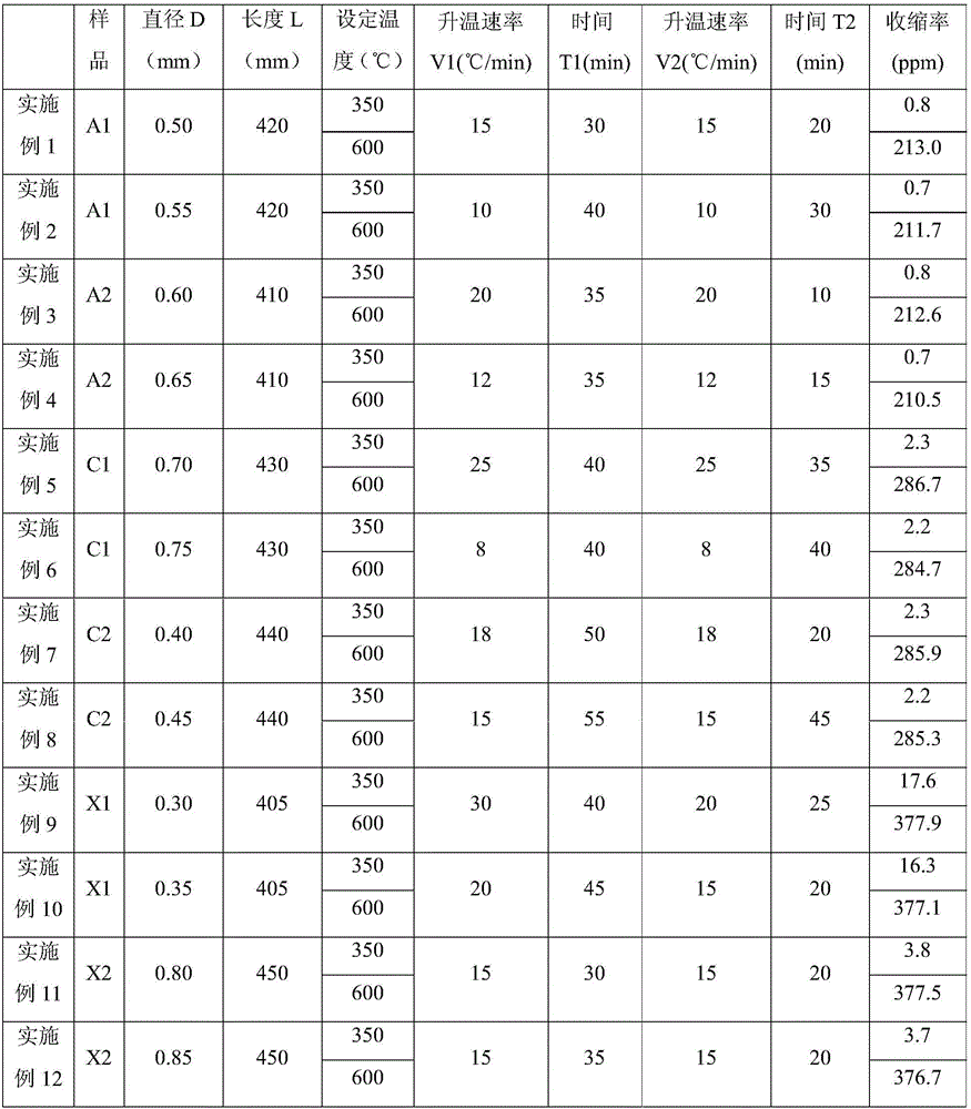
Embodiment 1-12

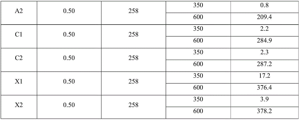
[0050] This example is used to illustrate the method for measuring glass shrinkage of the present invention.

[0051] (1) After melting the TFT-LCD glass substrate to be tested, use a wire drawing machine to draw glass filaments with a diameter of D (mm), cut the glass filaments to a length of L (mm), and burn the two ends of the obtained glass filaments Become a spherical shape with a diameter of 7mm to obtain the glass filament to be measured, and the length L1 of the glass filament to be heat-treated in the glass filament to be measured is 350mm;

[0052] (2) Wrap the glass fiber to be tested with thermal insulation cotton and put it into a precision annealing furnace, raise the temperature of the glass fiber to be tested to the annealing point temperature at a heating rate V1 (°C / min), and keep it warm at the annealing point temperature T1 (min), and then Cool down to 25°C with the furnace;

[0053] (3) After step (2) is annealed, the two ends of the glass fiber to be tes...


PUM

PropertyMeasurementUnit
diameteraaaaaaaaaa
lengthaaaaaaaaaa

Abstract

The invention relates to the technical field of glass production, and discloses a method for determining the shrinkage rate of glass. The method comprises the following steps: 1, preparing glass fibers to be determined, and determining the length L1 of heat treated glass fibers in the glass fibers to be determined; 2, carrying out heat treatment on the glass fibers to be determined, and determining the length change deltaL of the glass fibers before and after the heat treatment; and 3, determining the shrinkage rate C of the glass fibers to be determined, wherein C = deltaL / L1. The method has the advantages of accurate determination result, high reappearance, high precision, high result credibility, and provision of a shrinkage determination reference standard for the research and development process of plate glass.

Description

technical field [0001] The invention relates to the technical field of glass production, in particular to a method for measuring glass shrinkage. Background technique [0002] With the rapid development of flat panel display technology and the rapid popularization of portable electronic products such as notebook computers, tablet computers, smart phones and smart wearable devices, liquid crystal displays play an increasingly important role in them. High-quality liquid crystal display products are more accepted by the market. [0003] The glass substrate is an important part of the liquid crystal display device (LCD). In recent years, with the development of LCD technology, higher and higher requirements have been put forward for the performance of the glass substrate material. These requirements mainly depend on the method and manufacturing process of the liquid crystal display. For example, in an active matrix liquid crystal display (AM-LCD), thin film transistors (TFT) a...

Claims


Application Information

Patent Timeline
Patent Type & Authority Applications(China)
IPC IPC(8): G01N25/16G01B21/02
CPCG01B21/02G01N25/16
Inventor 王俊峰张广涛李俊锋闫冬成王丽红胡恒广
Owner WUHU DONGXU OPTOELECTRONICS EQUIP TECH
Learn More