

Flow temperature difference proportional cold energy distribution system and method
A cooling capacity distribution and temperature difference technology, which is applied in the field of flow temperature difference cooling capacity distribution system, can solve problems such as difficult measurement and calibration, difficulties, and heavy maintenance workload, so as to eliminate the interference of measurement principles, accurate measurement results, and sufficient theoretical basis Effect
- Summary
- Abstract
- Description
- Claims
- Application Information
AI Technical Summary
Problems solved by technology
Method used
Image

Examples
specific Embodiment approach 1
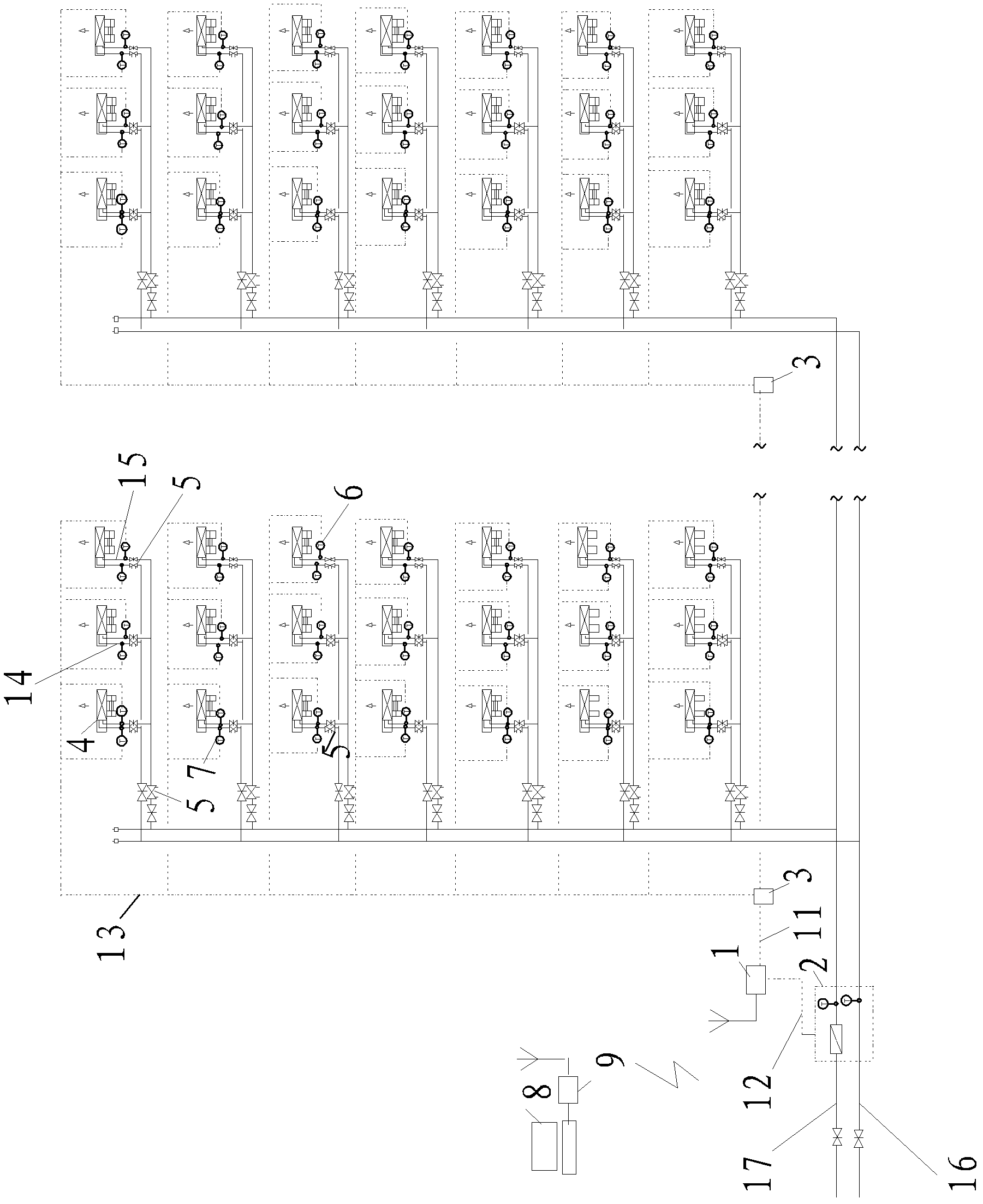
[0042] Specific implementation mode one: combine figure 1 Explain, a flow temperature difference proportional cooling capacity distribution system in this embodiment, the system includes a remote transmission module 1, a cooling capacity meter 2, a second signal transmission bus 12, a third signal transmission bus 13, and multiple unit temperature collectors 3. Several supply water temperature sensors 6, several return water temperature sensors 7 and several balance valves 5 with flow measurement function;
[0043] A balance valve 5 with a flow measurement function is provided on the end return water main pipe 14 of each user's fan coil unit 4 in a building (used to adjust the system balance, and record the user's fan coil unit 4 end balance The final flow value), a return water temperature sensor 7 is respectively arranged on the end return water main pipe 14 between each of the balance valves 5 and the corresponding fan coil unit 4, and a return water temperature sensor 7 is...
specific Embodiment approach 2
[0048] Specific implementation mode two: combination figure 1 To illustrate, multiple unit temperature collectors 3 in this embodiment transmit the measured supply and return water temperature data of each unit to the remote transmission module 1 by sharing a first signal transmission bus 11 or wirelessly. Others are the same as in the first embodiment.
specific Embodiment approach 3
[0049] Specific implementation mode three: combination figure 1 It is explained that the total flow and the total cooling capacity of the system measured by the cooling meter 2 of this embodiment are transmitted to the remote module 1 through the second signal transmission bus 12 . Others are the same as in the second embodiment.
PUM
 Abstract
Description
Claims
Application Information