Loop superposition magnetic circuit switch reluctance direct current motor
A technology of DC motor and switched reluctance, applied in synchronous machine parts and other directions, can solve the problems of increased production cost, unsatisfactory running stability, waste of materials, etc. Effect
- Summary
- Abstract
- Description
- Claims
- Application Information
AI Technical Summary
Problems solved by technology
Method used
Image
Examples
Embodiment 1
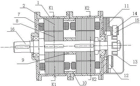
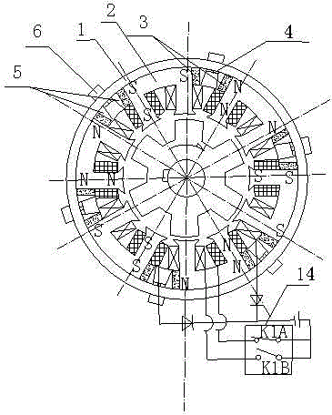
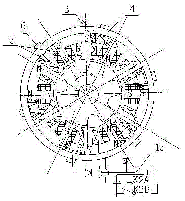
[0029] Such as Figure 1-6 As shown, the present invention includes a stator unit and a rotor unit installed in the stator unit, and the stator unit includes a plurality of split stator core laminations 2 installed in the casing 1, wound on the stator core laminations 2 protruding The stator winding 7 on the pole, the stator permanent magnet 3 and the ferrous magnetic conduction wedge assembly fixing the stator core lamination 2 and the stator permanent magnet 3, and the two ends of each independent stator core lamination 2 are placed on the surface Stator permanent magnets 3 of the same polarity, stator core laminations 2 and stator permanent magnets 3 form a unipolar stator core lamination unit, all stator core laminations on the stator unit 2 stator windings on salient poles 7 A-phase stator windings and B-phase stator windings are connected at intervals; the rotor unit includes rotor laminations 8 for driving the shaft 16 to rotate.
[0030] The casing is made of aluminum...
Embodiment 2
[0033]This embodiment is preferably as follows on the basis of the above-mentioned embodiment 1: the stator unit and the rotor unit are at least 2 and the number is equal, and the number of the stator unit is N and connected in series on the shaft 16, wherein the value range of N is A natural number between 2-4. In this embodiment, the number of groups of the stator unit and the rotor unit is 2 groups, and the two groups of stator units are respectively K1 and K2. The number of sets of the stator unit and the rotor unit can also be adjusted according to actual needs, and the use is more flexible. With the design of multiple independently working stator units and multiple groups of independently working rotor units, individual units can be designed and manufactured separately during design and manufacture, making the manufacturing easier, the manufacturing process optimized, and the production cost more reasonable.
Embodiment 3
[0035] This embodiment is preferably as follows on the basis of the above-mentioned embodiments: adjacent two groups of rotor units are staggered by 1 / N salient pole pitches in the circumferential distribution positions of the respective salient poles. In order to overcome the torque ripple generated when the A-phase stator winding and the B-phase stator winding commutate, that is, when the K1 rotor unit is at the commutation zero torque position, the K2 rotor unit is at the torque peak position, making the torque output more stable.
PUM
 Abstract
Description
Claims
Application Information
 - R&D
- Intellectual Property
- Life Sciences
- Materials
- Tech Scout
- Unparalleled Data Quality
- Higher Quality Content
- 60% Fewer Hallucinations
Browse by: Latest US Patents, China's latest patents, Technical Efficacy Thesaurus, Application Domain, Technology Topic, Popular Technical Reports.
© 2025 PatSnap. All rights reserved.Legal|Privacy policy|Modern Slavery Act Transparency Statement|Sitemap|About US| Contact US: help@patsnap.com


