A flow migration method and system based on network function virtualization scenarios

A network function virtualization and flow migration technology, which is applied in the field of flow migration methods and systems based on network function virtualization scenarios, can solve the problem of not responding in target network functions, inconsistent flow state functions, and inability to ensure that data packets reach the target. network and other problems, to achieve the effect of no packet loss and no out-of-order flow migration operation

Active Publication Date: 2019-04-30
INST OF COMPUTING TECH CHINESE ACAD OF SCI
View PDF6 Cites 2 Cited by
  • Summary
  • Abstract
  • Description
  • Claims
  • Application Information

AI Technical Summary

Problems solved by technology

[0006] Split / Merge(Rajagopalan S,Williams D,Jamjoom H,et al.Split / merge:System support for elastic execution in virtual middleboxes[C] / / Presented aspart of the 10th USENIX Symposium on Networked Systems Design and Implementation(NSDI 13). 2013:227-240.): When the migration starts, the controller instructs the Switch to immediately forward the data packets of the flow to be migrated to the controller for centralized caching, and then the controller copies the relevant state of the flow to be migrated in the source network function to the target In the network function, during this process, all the data packets of the migration flow will be cached in the controller. When the state copy is completed, the controller releases all the cached data packets to the target network function, and instructs the switch to directly forward the data packets to the target Network function, the whole process realizes the migration of flow and related states, but there are two problems. First, the packets released from the controller and the packets directly forwarded by the switch will be processed by the target network function out of order, which will cause network The error handling of the function, secondly, when starting to migrate the related flow state in the source network function, there are still some data packets that have been forwarded by the Switch but not yet processed by the source network function, these packets may update the flow state, but these states Updates to the target network function will never be reflected in the target network function, resulting in inconsistent flow state between the source and target network function
[0007] OpenNF: When the migration starts, the flow state is directly copied from the source network function. At this time, the source network function will forward the received migration flow data packet to the controller for caching. When the state copy is completed, the controller releases all cached packets. , the Switch also directly forwards the packet to the target network function, but at this time the target network function will first cache all the data packets from the Switch, and wait for all the data packets released from the controller to be processed before processing. Through this delicate The design can solve the problem of split / merge state inconsistency and packet disorder. However, this is a centralized system. When the migration scale is large, the controller will become the bottleneck of the entire system (single point processing and caching all Migration packets), in addition, the way migration packets are delivered to the target network function via the controller introduces additional forwarding
[0008] Improved OpenNF is different from OpenNF. The source network function only forwards the packets that upgrade the flow state to the controller for caching, which greatly reduces the cache pressure of the controller while ensuring state consistency. However, this method is still a centralized In addition, this method cannot guarantee that data packets will reach the target network function without disorder
[0009] like figure 1 As shown, the existing technology has shortcomings in terms of state consistency, migration efficiency, centralized caching requirements, and additional overhead of network functions.

Method used


Image

  • A flow migration method and system based on network function virtualization scenarios
  • A flow migration method and system based on network function virtualization scenarios
  • A flow migration method and system based on network function virtualization scenarios

Examples


Embodiment Construction

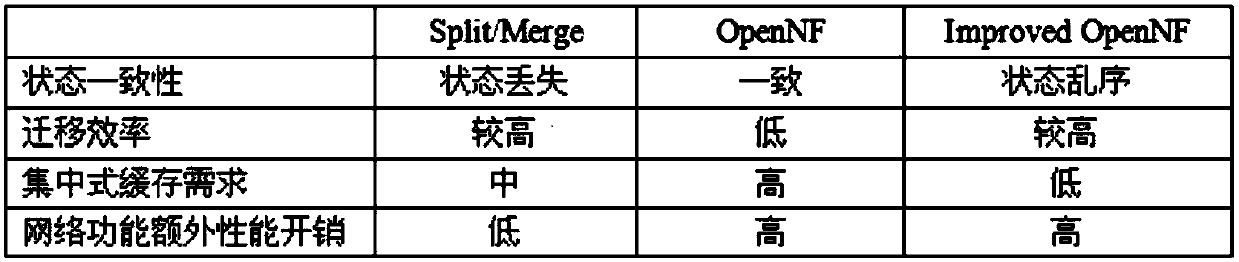
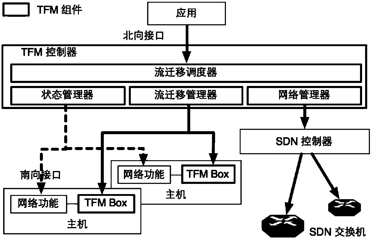
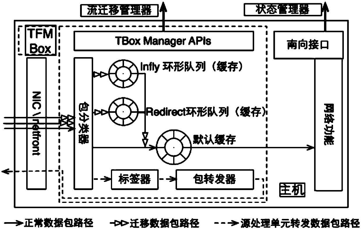
[0050] In order to solve the problems of state inconsistency, low migration efficiency, controller bottleneck, and network function overhead in the prior art when performing load migration in NFV, the present invention designs and implements a distributed architecture-based flow migration system (Transparent Flow Migration,TFM), such as Figure 2-1 As shown, each migration unit (TFM Box, Figure 2-2 ) based on a state machine triggered by multiple events ( Figure 2-3 ) to judge the migration state, and generate data packet processing rules, realize the distributed collaborative classification and processing of data packets, and then complete the migration of data packets. In addition, the state machine of the migration unit can support the out-of-order arrival of various events (asynchronous processing mechanism) , so as to decouple the two operations of state migration and data packet migration; the TFM controller provides a northbound migration interface to the application...


PUM


Abstract

The present invention proposes a flow migration method based on a network function virtualization scenario. The method includes deploying a source flow migration processing unit and a target flow processing unit at the source network function and the target network function respectively, and through the source flow migration processing unit Two labels are set in the header of the data packet with the network switching equipment, and the data packet is marked as four types, including normal class, in-fly class, last in-fly class, redirect class, and the described target flow migration processing unit uses based on The classifier of the label classifies the normal class, in-fly class, last in-fly class, and redirect class data packets; deploys a state machine in the flow migration processing unit to record the current migration state, and the source state machine is based on The migration state marks and forwards the data packets, and the target state machine places the four types of data packets respectively in the default cache, in-fly ring cache and redirect ring cache in the target flow processing unit according to the migration state and packet processing rules , and finally delivered to the target network function through the default cache.

Description

technical field [0001] The present invention relates to the field of network function virtualization and the field of software-defined network technology, and in particular to a flow migration method and system based on network function virtualization scenarios. Background technique [0002] With the evolution of the network architecture and the continuous development of services, more and more dedicated devices are deployed in the network, such as security devices such as firewalls, intrusion detection, and access authentication, and performance-enhancing devices such as load balancing and TCP acceleration. Same level as routing and switching equipment. The massive deployment of these dedicated devices not only increases the cost of purchase and operation, but also increases the difficulty of management, operation and maintenance. Moreover, the development cycle is long, which cannot meet the requirements of rapid innovation and dynamic deployment of networks and applicatio...

Claims


Application Information

Patent Timeline
Patent Type & Authority Patents(China)
IPC IPC(8): H04L29/08H04L12/803
CPCH04L47/125H04L67/1001H04L67/563H04L67/568
Inventor 王阳李振宇贺鹏谢高岗
Owner INST OF COMPUTING TECH CHINESE ACAD OF SCI
Why Eureka
Try Eureka