

glass laminate
A laminated body and glass technology, applied in the direction of glass/slag layered products, layered products, synthetic resin layered products, etc., can solve the problem of reduced handling of glass substrates, and achieve the effect of easy peeling and inhibition of decomposition
- Summary
- Abstract
- Description
- Claims
- Application Information
AI Technical Summary
Problems solved by technology
Method used
Image

Examples
no. 1 Embodiment approach >
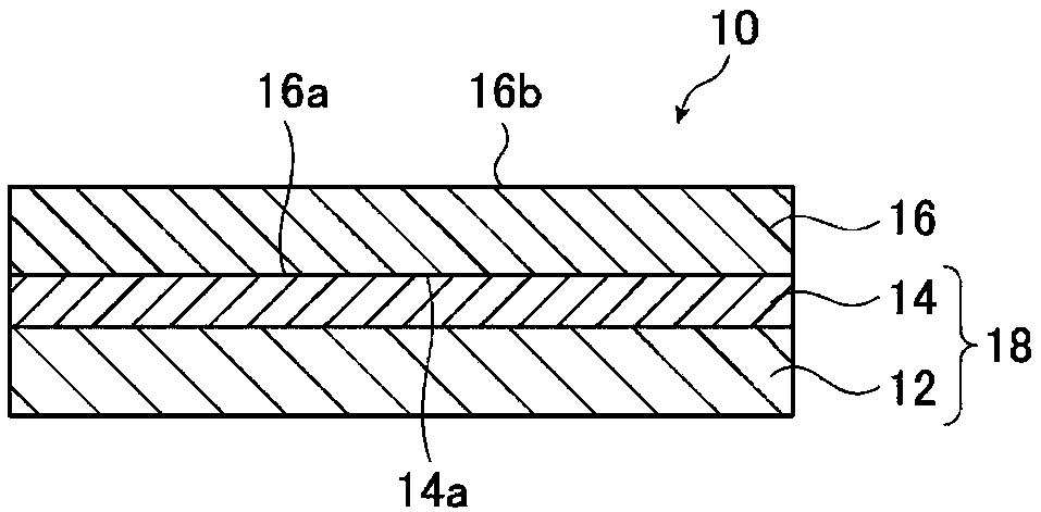
[0036] figure 1 It is a schematic cross-sectional view of the first embodiment of the glass laminate of the present invention.
[0037] like figure 1 As shown, the glass laminated body 10 is a laminated body having a layer of a support base material 12 and a layer of a glass substrate 16 with a silicone resin layer 14 interposed therebetween. One side of the silicone resin layer 14 is in contact with the layer of the support base 12 , and the other side is in contact with the first main surface 16 a of the glass substrate 16 .
[0038] The two-layer portion formed by the layer of the support base material 12 and the silicone resin layer 14 reinforces the glass substrate 16 in a member forming process for manufacturing members for electronic devices such as liquid crystal panels. In addition, the two-layer part which consists of the layer of the support base material 12 and the silicone resin layer 14 manufactured beforehand for manufacturing the glass laminated body 10 is ...
no. 2 Embodiment approach >
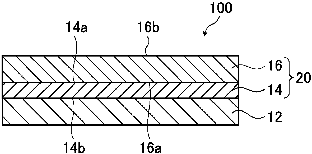
[0185] image 3 It is a schematic sectional view of 2nd Embodiment of the glass laminated body of this invention.
[0186] like image 3 As shown, the glass laminate 100 is a laminate having a layer of a support base 12 , a layer of a glass substrate 16 , and a silicone resin layer 14 interposed therebetween.
[0187] image 3 The glass laminate 100 shown is the same as the above figure 1 The glass laminate 10 shown is different in that the silicone resin layer 14 is fixed on the glass substrate 16, and the glass substrate 20 with the resin layer is directly bonded to the support substrate 12 with the silicone resin layer 14 in the glass substrate 20 with the resin layer. They are laminated (closely bonded) on the supporting base material 12 in a peelable manner. There is a difference in the peel strength (that is, the stress required for peeling) between the fixation and the peelable adhesion, and the fixation means that the peel strength is higher than that of the adhes...
Embodiment
[0235] Hereinafter, although an Example etc. are used and the present invention is demonstrated concretely, this invention is not limited to these examples. In addition, in this production example, evaluation of curable organopolysiloxane was performed according to the items and methods shown below.
[0236] (1) Analysis of bonding state of silicon atoms in curable organopolysiloxane (proportion of T units)
[0237] Using NMR analysis equipment (solution 29 Si-NMR: JEOL RESONANCE Co., Ltd. make, ECP400) The ratio of T1-T3 was calculated|required.
[0238] The specific solution of T1~T3 29 The peak area ratios of Si-NMR were obtained respectively. The measurement conditions were set as follows: a pulse width of 20 microseconds, a pulse repetition waiting time of 30 seconds, and an accumulation count of 256 scans. Add 0.1wt% of Cr(acac) as a relaxation agent to a solution prepared with a concentration of 30wt% using toluene as a solvent 3 . For the reference of the chemica...
PUM
| Property | Measurement | Unit |
|---|---|---|
| Thickness | aaaaa | aaaaa |
| Thickness | aaaaa | aaaaa |
| Thickness | aaaaa | aaaaa |
Abstract
Description
Claims
Application Information