Soymilk machine cup body assembly and soymilk machine

A soymilk machine and cup technology, which is applied in kitchen utensils, household utensils, beverage preparation devices, etc., can solve the problems of heat loss, achieve the effects of small energy loss, increase the probability of collision with materials, and improve the crushing efficiency

Active Publication Date: 2019-05-21
JOYOUNG CO LTD
View PDF11 Cites 0 Cited by
  • Summary
  • Abstract
  • Description
  • Claims
  • Application Information

AI Technical Summary

Problems solved by technology

Because, during the heating process of the heating element, a considerable part of the heat will be dissipated into the atmosphere due to the heat absorption of the air, resulting in heat loss.

Method used


Image

  • Soymilk machine cup body assembly and soymilk machine
  • Soymilk machine cup body assembly and soymilk machine
  • Soymilk machine cup body assembly and soymilk machine

Examples


Embodiment 1

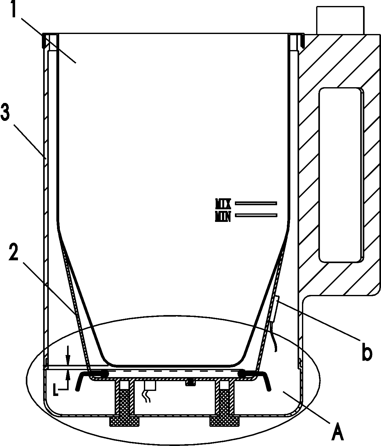
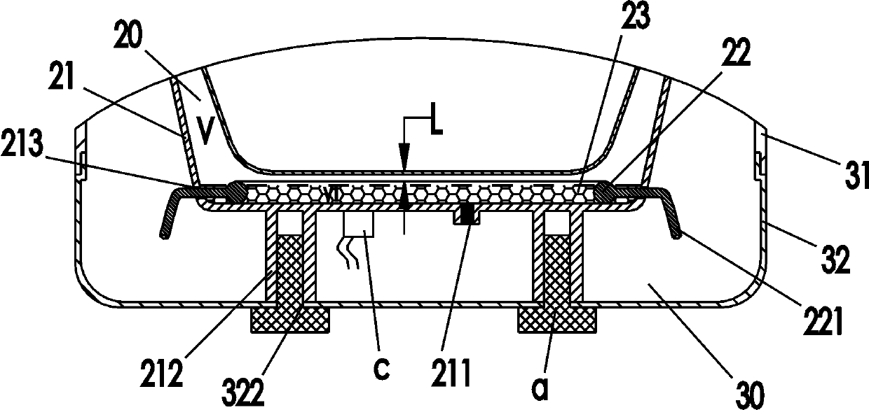
[0026] Such as figure 1 , figure 2 Shown is a schematic structural view of the first embodiment of the present invention. A soymilk machine cup assembly, the soymilk machine cup assembly includes a milk cup 1, a superconducting heating device 2 arranged at the bottom of the milk cup 1, and a superconducting heating device 2 installed on the outside of the milk cup 1 and accommodated in the The heat-insulating shell 3 of its inner cavity, the superconducting heating device 2 includes a housing 21 formed with a vacuum chamber 20, a heating body 22 arranged in the vacuum chamber 20 and a superconducting medium injected into the vacuum chamber 20 23. An injection hole 211 is provided on the outer wall of the housing 21, through which the superconducting medium 23 is injected into the vacuum cavity 20, and after the injection is completed, the injection hole 211 is sealed.

[0027] In this embodiment, the shell 21 is welded and covered on the lower outside of the pulp cup 1, and...

Embodiment 2

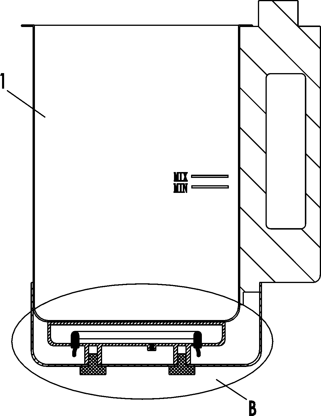
[0037] Such as image 3 , Figure 4 Shown is the second embodiment of the present invention. The difference from Embodiment 1 is that in this embodiment, the superconducting heating device is located on the bottom outer surface of the plasma cup to heat the bottom of the plasma cup, and the heating body 22 is directly fixed to the through hole 213 of the housing 21 , and the sealing process between the heating body 22 and the through hole 213, the connecting wire 221 drawn from the end of the heating body 22 is directly exposed and connected in series with the fuse and the temperature controller (not shown in the figure). And the vacuum chamber 20 is only formed by sealing the housing 21, and the outer surface of the bottom of the pulp cup 1 is closely attached to the outer wall of the housing 21, and at the same time, the heat insulation shell is directly fixed on the bottom of the pulp cup 1 The base 32 wraps the superconducting heating device in its inner cavity 30 .

[...


PUM


Abstract

The invention relates to small kitchen electrical appliances and accessories thereof, in particular to a soybean milk machine cup body assembly and a soybean milk machine with the cup body assembly. The soybean milk machine cup body assembly comprises a soybean milk containing cup, a superconductive heating device arranged at the lower portion of the soybean milk containing cup, and a thermal insulation shell installed outside the soybean milk containing cup, wherein the superconductive heating device is contained in an inner cavity of the thermal insulation shell. The superconductive heating device comprises a shell forming a vacuum cavity, a heating body arranged in the vacuum cavity, and a superconductive medium injected in the vacuum cavity. A material injection hole is formed in the outer wall of the shell. The superconductive medium is injected in the vacuum cavity through the material injection hole. After injection is completed, the material injection hole is sealed. By means of the soybean milk machine cup body assembly and the soybean milk machine with the cup body assembly, heating power is low, heating efficiency is high, heating is uniform, the phenomenon that soybean milk is burnt in a pot and at the bottom can not easily happen, and made beverages are high in crushing fineness and smooth in taste.

Description

technical field [0001] The invention relates to small kitchen appliances and parts thereof, in particular to a soybean milk machine cup body assembly and a soybean milk machine with the soybean milk machine cup body assembly. Background technique [0002] The Chinese patent number is "ZL200820206018.7", and the invention patent named "a soybean milk machine" discloses that the container of the soybean milk machine is provided with an outer barrel, and the outer barrel and the container are separated, and the heating element is arranged at the bottom of the outer barrel. And / or the inner part, a superheater is arranged on or near the heating surface of the heating element in the outer barrel, and the container slurry is heated by the superheater. Utilizing the high-efficiency thermal conductivity (thermal resistance close to zero) and isothermal properties of the superconducting heat pipe, it can form a real three-dimensional surrounding constant temperature heating for the b...

Claims


Application Information

Patent Timeline
Patent Type & Authority Patents(China)
IPC IPC(8): A47J31/00A47J31/44A47J31/54
Inventor 王旭宁黄启浪刘爽
Owner JOYOUNG CO LTD
Why Eureka
Try Eureka