
Lateral lift pipe quick cyclone separation design method and reactor

A technology of rapid separation and design method of swirl flow, which is applied in the fields of petrochemical industry and fluidization, and can solve the problems of shortening oil and gas residence time, coking and coking in settlers.

Inactive Publication Date: 2016-10-05
刘英聚
View PDF0 Cites 0 Cited by
  • Summary
  • Abstract
  • Description
  • Claims
  • Application Information

AI Technical Summary

Problems solved by technology

The coarse rotary leg discharges the catalyst under the condition of positive pressure difference, and discharges 15% to 30% of oil and gas at the same time. This part of oil and gas is discharged from the lower part of the settler and then flows slowly to the upper part for a residence time of 40 to 80 seconds. There are obvious excessive thermal cracking, condensation and other reactions, resulting in a decrease in the yield of light oil, and even coking in the settler when processing heavy oil
Some devices extend the rough-spin riser pipe upwards to the vicinity of the top-swirl inlet. This scheme greatly shortens the residence time of the oil and gas mainstream, but 15% to 30% of the oil and gas discharged from the coarse spin leg stays longer in the settler (80 to 110 seconds), the settler has a tendency to coke more seriously
Coaxial FCC device or side-by-side single riser or double riser device. The outlet of the riser adopts rough rotation and quick separation. When processing heavy oil, part of the oil gas discharged from the coarse rotation leg stays in the settler for as long as 80-110 Seconds lead to serious coking in the settler, which has become a key issue affecting the long-term operation of heavy oil FCC units
[0003] Parallel catalytic cracking unit, when adding a fast bed reactor on the upper part of the riser to improve gasoline quality, the fast bed reactor is arranged between the bottom end of the stripping section and the upper end of the riser (cracking section), and the existing parallel catalytic cracking unit This section of space cannot meet the height requirements of the fast bed reactor, that is, adding a fast bed reactor to a conventional parallel catalytic cracking unit cannot be realized

Method used


Image

  • Lateral lift pipe quick cyclone separation design method and reactor
  • Lateral lift pipe quick cyclone separation design method and reactor
  • Lateral lift pipe quick cyclone separation design method and reactor

Examples


Embodiment Construction

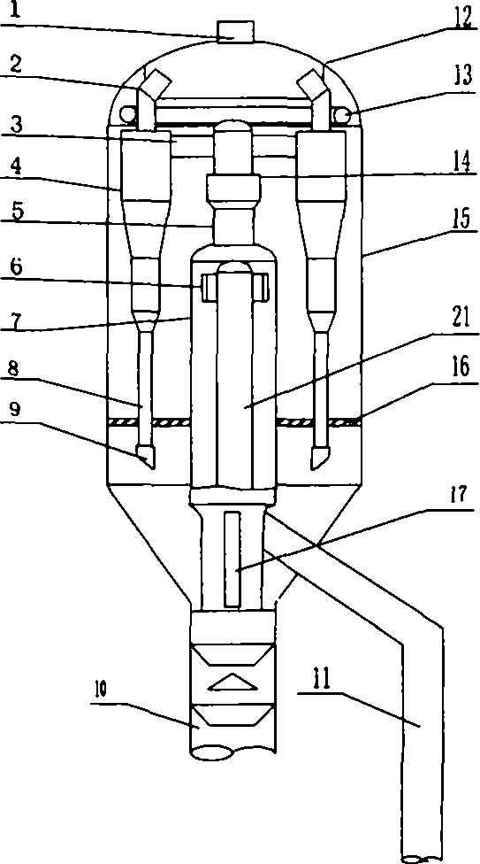
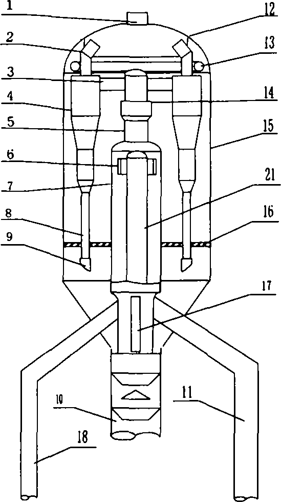
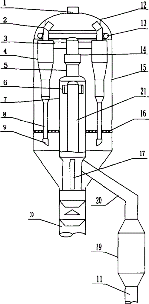
[0021] See Figure 1 ~ Figure 3 , figure 1 It is a single-side riser cyclone fast separation reactor, figure 2 It is a double-sided riser cyclone fast separation reactor, image 3 It is a side riser cyclone fast separation reactor with a fast bed reactor. The upper part of the settler 15 has an oil and gas outlet 1, a gas collection chamber 12 and an anti-coking steam ring pipe 13. The upper end of the central feeding pipe 21 extends into the inside of the sealing cover 7 and is connected with the cyclone 6 . The sealing cover 7 is a cylindrical structure, and the bottom is provided with some air windows 17, and the upper end is connected with the top rotation 4 through the sealing cover exhaust pipe 5 (compensator 14 is provided), the top rotation inlet pipe 3. The upper end of the top rotation 4 is connected to the gas collection chamber 12 through the top rotation exhaust pipe 2, and the lower end is connected to the dip leg 8 and the wing valve 9. An isolation plate ...


PUM


Abstract

The invention discloses a lateral lift pipe quick cyclone separation design method, and belongs to the technical field of petrochemical engineering and fluidization. The method is used for solving the problems that an oil gas excessive thermal cracking settler of a lateral lift pipe device cokes, and layout is difficult as a quick bed reactor needs to be additionally arranged on a parallel type FCC device. A settler, a lateral lift pipe and a top cyclone are involved in the method. The method is characterized in that a built-in quick cyclone separator is arranged, the upper portion of the lateral lift pipe is horizontally or obliquely folded to stretch into the settler from the lower portion of the settler and be connected with the built-in quick cyclone separator, the built-in quick cyclone separator is connected with the top cyclone in an airtight mode, and a steam isolation part is arranged in the middle upper portion of the settler. The invention further provides the foldable lift pipe, the built-in quick cyclone separator and other equipment for implementing the method. When a single or double lift pipe is laterally arranged or a quick bed reactor is additionally arranged on an FCC device, the built-in quick cyclone separator can be adopted, excessive thermal cracking of oil gas can be reduced, and coking of the settler can be avoided.

Description

technical field [0001] The invention belongs to the technical fields of petrochemical industry and fluidization, and in particular relates to a method for designing a swirl quick separation of a side riser and a reactor. Background technique [0002] The outlet of the riser reactor of the catalytic cracking unit in the refinery is equipped with a gas-solid rapid separation device, which is used to realize the rapid separation of oil gas and catalyst and terminate the cracking reaction. There are 1 to 4 primary cyclone separators (referred to as coarse cyclone) at the outlet of the riser reactor in most devices. The coarse rotary leg discharges the catalyst under the condition of positive pressure difference, and discharges 15% to 30% of oil and gas at the same time. This part of oil and gas is discharged from the lower part of the settler and then flows slowly to the upper part for a residence time of 40 to 80 seconds. There are obvious excessive thermal cracking, condensat...

Claims


Application Information

Patent Timeline
Patent Type & Authority Applications(China)
IPC IPC(8): B01J8/24B01J8/18C10G11/18C10G11/14B01D45/12
Inventor 刘英聚
Owner 刘英聚
Learn More