Piezoelectric spray head, its processing method, and spraying equipment including the same

A technology of piezoelectric ceramics and nozzles, applied in the field of piezoelectric ceramics, can solve problems such as low output force, easy wear of nozzle parts, and small deformation of ink chambers, so as to increase initial speed, improve work efficiency, and have a wide range of applications Effect

Active Publication Date: 2018-05-11
PAIHE SCI & TECH HLDG CO LTD BEIJING +1
View PDF13 Cites 0 Cited by
  • Summary
  • Abstract
  • Description
  • Claims
  • Application Information

AI Technical Summary

Problems solved by technology

[0002] The nozzle is the core part of the inkjet printer or dispensing machine, which accounts for the highest cost and the highest technical content. It is blank from research and development to manufacturing in China and completely depends on imports. However, the structure of foreign nozzles is complex and the preparation process is also very complicated. , the dependence on ultra-precision processing equipment is very strong, and the price of the nozzle is expensive; in addition, the output displacement and output force of foreign nozzles are low, and the scope of application of the nozzle is limited; and the parts of the nozzle are easy to wear and have a short life
[0003] Take the Epson piezoelectric nozzle as an example, such as figure 1 and figure 2 As shown, the nozzle plate and the ink chamber of the Epson piezoelectric nozzle are made of MEMS production technology, the structure and processing technology are complicated, the processing equipment is expensive, and the cost of the nozzle is high; the piezoelectric ceramic in the structure of the Epson piezoelectric nozzle is 1 micron thick The piezoelectric ceramic film is limited by the preparation process, and its own density is relatively low. When it is deformed by electricity, it will not produce a large output displacement, so that the output force is low, and the material of the Epson piezoelectric nozzle is mainly semiconductor silicon. , the silicon material has high rigidity, and the deformation range of the ink chamber is small, which further reduces the output force. Due to the decrease in the output force, the Epson piezoelectric nozzle is only suitable for home and office printing, not suitable for industrial ceramic inkjet printing or those that require high ejection force. Dispensing printing, etc.; the entire piezoelectric ceramic film of the Epson piezoelectric nozzle is bonded to the surface of the ink chamber substrate. When the piezoelectric ceramic film is deformed, it will cause deformation of the entire ink chamber, making parts such as the ink chamber easy to wear , short life

Method used


Image

  • Piezoelectric spray head, its processing method, and spraying equipment including the same
  • Piezoelectric spray head, its processing method, and spraying equipment including the same
  • Piezoelectric spray head, its processing method, and spraying equipment including the same

Examples


Embodiment 1

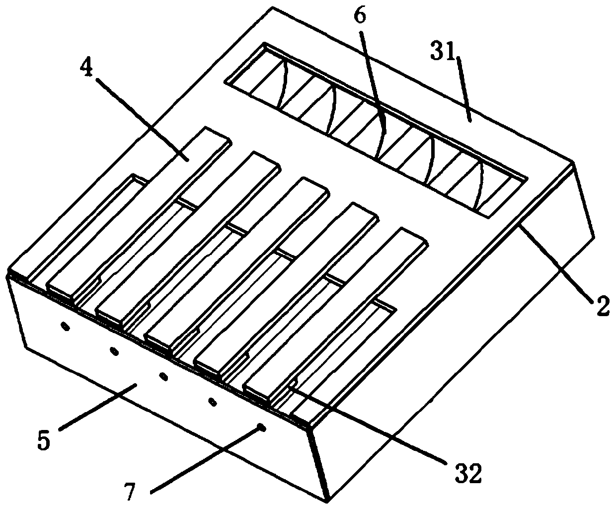
[0050] The ink tank 1 is a tank body with one end closed and one end open, wherein:

[0051] There is a window at the closed end of the ink tank 1 on the flexible diaphragm 2 and the support 31 to form the ink inlet 6, such as Image 6 As shown; or, the bottom of the closed end of the ink tank is provided with a through hole to form an ink inlet;

[0052] The nozzle 7 is arranged on the nozzle plate 5, and the nozzle plate 5 is glued to the end surface of one end of the opening of the ink tank 1;

[0053] The nozzle is set on the nozzle plate. When the nozzle fails, only the nozzle plate needs to be replaced instead of the entire piezoelectric nozzle.

Embodiment 2

[0055] The ink tank is a tank body with one end closed and one end open, wherein:

[0056] The end surface of one end of the opening of the ink tank is used as an ink inlet;

[0057] One end of the opening is used as the ink inlet, and no additional ink inlet is required, which is simple and convenient;

[0058] There is a small hole on the end surface or the bottom surface of the closed end of the ink tank as a nozzle;

[0059] A small hole is arranged on the end surface or the bottom surface of the closed end of the ink tank as a nozzle, and no additional nozzle plate is needed.

Embodiment 3

[0061] The ink tank is a tank body closed at both ends, wherein:

[0062] A window is opened at one end of the ink tank on the flexible diaphragm and the support to form an ink inlet; or, a through hole is opened at the bottom of one end of the ink tank to form an ink inlet;

[0063] The end surface or the bottom surface of the other end of the ink tank is provided with a small hole as a nozzle;

[0064] There is a small hole on the end surface or the bottom surface of the other end of the ink tank as a nozzle, and no additional nozzle plate is needed.


PUM


Abstract

The invention discloses a piezoelectric nozzle, a processing method thereof, and a spraying equipment including the nozzle, belonging to the field of piezoelectric ceramics. The piezoelectric nozzle includes at least one ink tank, and the ink tank is covered with a flexible diaphragm to form ink One end of the ink chamber is provided with an ink inlet, and the other end is provided with a nozzle. The flexible diaphragm is provided with a piezoelectric ceramic cantilever beam that adopts a d31 in-plane transverse bending deformation mode corresponding to the ink chamber. One end of the electric ceramic cantilever beam is fixed close to the ink inlet, and the other end is close to the nozzle, and the piezoelectric ceramic cantilever beam is connected with a drive circuit. Compared with the prior art, the piezoelectric nozzle of the present invention has high output force, wide application range, less wear and tear of parts and long service life.

Description

technical field [0001] The invention relates to the field of piezoelectric ceramics, in particular to a piezoelectric spray head, a processing method thereof, and spraying equipment including the spray head. Background technique [0002] The nozzle is the core part of the inkjet printer or dispensing machine, which accounts for the highest cost and the highest technical content. It is blank from research and development to manufacturing in China and completely depends on imports. However, the structure of foreign nozzles is complex and the preparation process is also very complicated. , The dependence on ultra-precision processing equipment is very strong, and the price of the nozzle is expensive; in addition, the output displacement and output force of the foreign nozzle are low, and the scope of application of the nozzle is limited; and the parts of the nozzle are easy to wear and have a short life. [0003] Take the Epson piezoelectric nozzle as an example, such as figur...

Claims


Application Information

Patent Timeline
Patent Type & Authority Patents(China)
IPC IPC(8): B41J2/045B41J2/14
Inventor 仲作金崔宏超张淑兰
Owner PAIHE SCI & TECH HLDG CO LTD BEIJING
Why Eureka
Try Eureka