Device for electronic beams to assist plasma in sputtering coating of flexibility copper-clad plate

A flexible copper-clad laminate and plasma sputtering technology, which is applied in the equipment field of ion sputtering flexible copper-clad laminates, can solve problems such as unusable, high probability of scrap, poor film adhesion, etc., to achieve improved peel strength and improved production efficiency , The effect of reducing manufacturing costs

Active Publication Date: 2016-10-05
广东腾胜科技创新有限公司
View PDF4 Cites 1 Cited by
  • Summary
  • Abstract
  • Description
  • Claims
  • Application Information

AI Technical Summary

Problems solved by technology

[0002] The flexible copper-clad laminates currently used in the electronics industry use coating methods, lamination methods, etc., but because ultra-thin copper foil cannot be produced, it has gradually developed into a new preparation method that uses vacuum sputtering and electroplating, namely Using the PI film as the base material, the thin metal layer (seed layer) is plated on the PI film by vacuum sputtering, and then the thickness of copper on the thin metal layer is increased by electroplating.
[0003] However, after the thin metal layer is plated by the current vacuum magnetron sputtering method, due to the poor adhesion of the film layer, in the electroplating process of the subsequent process, the film layer is aged or even peeled off in the local area of ​​the sputtered copper film.
Even if there is no peeling off of the film layer during the electroplating process, the copper foil cannot be used because the peel strength of the copper foil cannot meet the requirements of downstream manufacturers after it is finished, reflecting the problem of poor bonding between the seed layer and the substrate , leading to a higher probability of scrap, and the quality cannot meet the standard

Method used


Image

  • Device for electronic beams to assist plasma in sputtering coating of flexibility copper-clad plate

Examples


Embodiment Construction

[0022] The present invention will be further described in detail in conjunction with the accompanying drawings and specific embodiments.

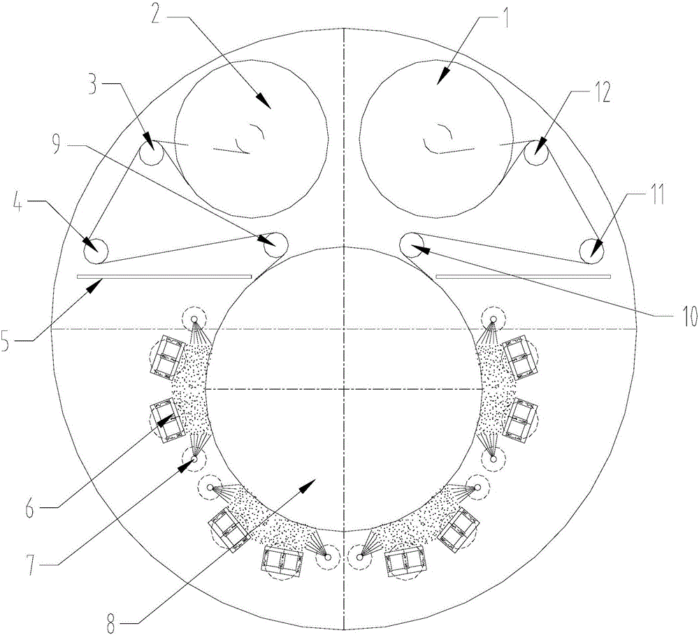
[0023] For the convenience of description, the up, down, left, and right directions mentioned below are the same as figure 1 The up, down, left, and right directions are the same.

[0024] combine figure 1 As shown, the equipment for electron beam-assisted plasma sputtering of flexible copper-clad laminates includes a vacuum chamber and partitions all arranged in the vacuum chamber, multiple electron beam auxiliary devices, multiple pairs of magnetron targets, multiple high-frequency AC power supplies, and base Materials, running circuit components used to control the operation of substrates. The running line assembly includes unwinding rollers, first guide rollers, first detection rollers, second guide rollers, water-cooled drums, third guide rollers, second detection rollers, fourth guide rollers, Winding roller. Multiple pairs of mag...


PUM


Abstract

The invention relates to a device for electronic beams to assist plasma in sputtering coating of a flexibility copper-clad plate, and belongs to the technical field of electronic industry. The device comprises a vacuum chamber and further comprises partition plates, a plurality of electronic beam assisting devices, a plurality of pairs of magnetic control targets, a base material and a running line assembly, all of which are arranged in the vacuum chamber, wherein the running line assembly is used for controlling running of the base material. The running line assembly comprises an unwinding roller, a first guide roller, a first detection roller, a second guide roller, a water cooling drum, a third guide roller, a second detection roller, a fourth guide roller and a winding roller, all of which are sequentially arranged along the base material running path. The multiple pairs of magnetic control targets are arranged in the circumferential direction of the circumferential surface of the water cooling drum. Each of the two sides of each pair of magnetic control targets is provided with one electronic beam assisting device. The unwinding roller, the first guide roller, the first detection roller, the second guide roller, the third guide roller, the second detection roller, the fourth guide roller and the winding roller are located above the partition plates, and the electronic beam assisting devices and the magnetic control targets are located below the partition plates. According to the device, the deposition quality of a metal thin layer is effectively improved, and the binding force between the metal thin layer and the base material is greatly improved.

Description

technical field [0001] The invention relates to the field of electronics industry such as flexible circuit boards and flexible touch screens, and in particular to equipment for electron beam-assisted plasma sputtering of flexible copper-clad boards. Background technique [0002] The flexible copper-clad laminates currently used in the electronics industry use coating methods, lamination methods, etc., but because ultra-thin copper foil cannot be produced, it has gradually developed into a new preparation method that uses vacuum sputtering and electroplating, namely The PI film is used as the base material, and a metal thin layer (seed layer) is plated on the PI film by vacuum sputtering, and then the thickness of copper on the metal thin layer is increased by electroplating. [0003] However, after the metal thin layer is plated by the current vacuum magnetron sputtering method, due to the poor adhesion of the film layer, in the electroplating process of the subsequent proce...

Claims


Application Information

Patent Timeline
Patent Type & Authority Applications(China)
IPC IPC(8): C23C14/35C23C14/56
CPCC23C14/355C23C14/562
Inventor 朱文廓朱刚劲朱刚毅
Owner 广东腾胜科技创新有限公司
Why Eureka
Try Eureka