

Radar liquidometer calibration device
A technology of radar liquid level gauge and calibration device, which is applied in the field of liquid level gauge, can solve the problems of track parallelism and verticality that have a great influence on the detection results, high precision requirements for track laying, and radar waves that cannot be received, etc., to achieve reduction Interference, high displacement detection accuracy, improve the effect of measuring distance
Inactive Publication Date: 2016-10-05
SHENZHEN EXSAF ELECTRONICS CO LTD
View PDF6 Cites 7 Cited by
- Summary
- Abstract
- Description
- Claims
- Application Information
AI Technical Summary
Problems solved by technology
The characteristic of this kind of verification or calibration device is that the laying accuracy of the track is high, which leads to high cost, and the parallelism and perpendicularity of the track have a great influence on the detection results. In severe cases, the radar wave cannot be received after being reflected.
Method used
View moreImage
Smart ImageViewing Examples

Examples
Embodiment 1
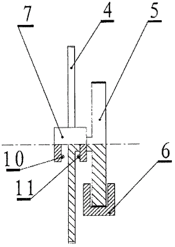
[0025] In this embodiment, the width of the rectangular tooth groove is 2.5 mm, R8=286.6 mm, R9=28.66 mm, namely: K=10. The overall resolution of the displacement sensor is 0.5 mm. It can be completely used for testing or calibrating liquid level gauges with a liquid level resolution of ±2.5 mm.
Login to View More PUM
 Abstract
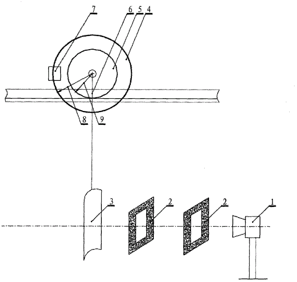
The invention relates to a radar liquidometer calibration device. The radar liquidometer calibration device is simple in structure, is easy to operate, is low in demand for the levelness of guide rails, and is high in resolution. The radar liquidometer calibration device includes a horizontal guide rail; the horizontal guide rail is provided with a sliding base; a metal radar wave reflection plate is hanged under the base and is used for reflecting radar wave emitted by a radar liquidometer; the base is provided with a displacement sensing disc which can synchronously rotate while the base moves on the horizontal guide rail; the displacement sensing disc is coaxially connected to a raster sensing disc; 360 gaps are evenly formed in the perimeter of the raster sensing disc; and the base is provided with a displacement pulse conversion device which is corresponding to the gaps of the e raster sensing disc.
Description
technical field [0001] The invention relates to the field of liquid level gauges, in particular to a calibration device for radar liquid level gauges, which is a verification or calibration device for detecting radar liquid level gauges with a relatively high liquid level range. Background technique [0002] At present, in the field of automatic measuring instruments, the verification or calibration of radar level or liquid level detection instruments usually uses a simulated metal radar wave reflector on two relatively parallel rails, and is fixedly installed at the other end of the rails to be verified or For the calibrated radar level gauge, the radar level gauge is verified or calibrated by moving the position of the metal radar wave reflector. The measurement of the liquid level is converted into the measurement of the distance, thereby realizing the verification or calibration of the radar level gauge. The standard distance or displacement is obtained by the displacem...
Claims
Login to View More Application Information
Patent Timeline
 Patent Type & AuthorityApplications(China)
IPC IPC(8): G01F25/00
Inventor陈士学白虹妍徐昌鸿张炳武
OwnerSHENZHEN EXSAF ELECTRONICS CO LTD